Why WFI Reject Is the Opposite of Conventional MBR Feed
A submerged PVDF flat-sheet MBR (0.1 μm pore size) is the preferred configuration for Water-for-Injection (WFI) system reject because the reject has low BOD/COD but high TDS and residual sanitizers, conditions where submerged aeration-driven scouring outperforms sidestream cross-flow on energy and fouling. For reuse, the MBR effluent is typically polished by RO (up to 95% recovery) to remove residual ions; for discharge, the MBR alone meets most BOD/TSS effluent limits.
WFI reject is the 5–20% concentrated side-stream left over when a pharma or biotech plant generates WFI through multi-effect distillation (MED), vapor-compression (VC) stills, or RO + EDI. It carries everything the WFI process removed from the feedwater: hardness ions, silica, residual sanitizers, and trace organics that failed the distillation or membrane cut. Designers who treat it like municipal wastewater overbuild the plant, over-aerate the basin, and still end up with a membrane that fouls in weeks. The matrix inverts the usual MBR design logic.
| Parameter | WFI Reject (typical) | Municipal MBR Feed |
|---|---|---|
| BOD/COD | <100 mg/L (often <50) | 200–600 mg/L BOD |
| TDS | 500–5,000 mg/L | 500–1,500 mg/L |
| Temperature | 40–60 °C (still/VC reject) | 15–25 °C |
| Sanitizer residuals | 1–50 mg/L H₂O₂ or peracetic acid | None / trace |
| Particulates | Near-sterile, low TSS | 150–400 mg/L TSS |
| Biological demand | Minimal, oligotrophic | High, carbon-rich |
At <100 mg/L BOD, the MBR is a polishing barrier rather than a biodegradation workhorse. Aeration demand drops, MLSS targets fall, and flux must be derated because osmotic drag from high TDS tightens effective pore throughput. A design flux of 8–12 LMH is realistic here, versus 15–25 LMH for municipal MBRs (HydropureWater field data, 2026). High temperature is a hidden asset that keeps viscosity low and helps scour foulants, provided the membrane polymer tolerates continuous 40–60 °C service.
Submerged vs Sidestream MBR: Which Fits WFI Reject?
A submerged PVDF flat-sheet MBR is the default choice for WFI reject, with sidestream tubular systems reserved for cases where TSS exceeds ~3,000 mg/L or the reject has cooled below 30 °C. Submerged aeration supplies both oxygen and membrane scouring in a single step, while sidestream cross-flow burns 10–20× more energy per cubic meter of permeate (per the DF-series PVDF flat-sheet membrane module spec, 2026) and adds shear heating to a stream that is already hot.
| Criterion | Submerged PVDF Flat-Sheet (DF) | Sidestream Tubular / Cross-Flow |
|---|---|---|
| Specific energy demand | 0.3–0.8 kWh/m³ permeate | 4–10 kWh/m³ permeate |
| Design flux (WFI reject) | 8–12 LMH | 15–30 LMH (but fouled quickly) |
| Temperature tolerance | Continuous 40 °C; tolerant of 60 °C spikes | Pump shear adds 3–8 °C; risks thermal damage to PES/PSU |
| Sanitizer tolerance | PVDF: 1–2 mg/L free Cl₂, pH 2–10 | Most tubular PES degrades above 0.5 mg/L Cl₂ |
| Footprint | Higher (large aeration tank) | Compact skid, external loop |
| MLSS target | 4,000–6,000 mg/L | 8,000–12,000 mg/L |
| HRT | 8–12 h | 2–4 h loop residence |
| Maintenance | CIP in place, cassette lift | Loop disassembly, pump rebuild |
On a low-COD, high-TDS feed, the sidestream configuration cannot justify its energy cost. Cross-flow velocity only helps when there are particulates to keep in suspension; WFI reject is already near-sterile. The submerged cassette sits in the aeration basin and uses coarse-bubble scouring at 60–80 m³ air per m² membrane area per hour to keep the surface clear. PVDF is the only practical material here because PES and polysulfone degrade under the residual H₂O₂ and peracetic acid that periodically spike the reject stream. An DF-series PVDF flat-sheet membrane module at 0.1 μm nominal pore size is the working spec; the integrated submerged MBR system packages the basin, cassette frame, blowers, and PLC into a single skid for flows of 10–2,000 m³/day.
For plants familiar with sidestream systems from food or dairy work, this transition may seem counterintuitive—flux numbers are lower, basin volume is larger, and aeration blower sizing dominates the electrical load. However, this is the correct trade for this matrix. Specifying a sidestream unit for WFI reject results in unnecessary pump wear and energy heat.
Reuse Path: MBR + RO Polishing to Recover Boiler-Feed and Cooling-Tower Make-Up
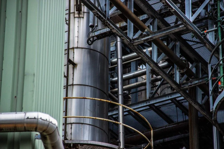
An MBR followed by an industrial RO polish converts a disposal liability into a recovered-water asset suitable for low-pressure boiler feed and cooling-tower make-up. The process flow is straightforward: equalization (8–24 h) → pH/temperature trim → submerged MBR → 5 μm cartridge guard → industrial RO polishing system at up to 95% recovery → optional mixed-bed polish → utility distribution.
Recovered water from the MBR + RO train typically meets <50 mg/L TDS, <5 mg/L silica, and conductivity <100 μS/cm (HydropureWater RO operating data, 2026). This envelope supports cooling-tower cycles of concentration ≥4 and low-pressure boiler feed after standard chemical conditioning (oxygen scavenger, amine). The RO concentrate stream—5–10% of the feed—carries the rejected salts and can be directed to cooling-tower blowdown, used as deasher water in a ZLD/crystallization train, or sent to the sewer if local TDS limits permit.
Recovered water for non-compendial reuse does not need to meet the WFI monograph under USP or EP; the relevant framework is plant utility specifications and local indirect-discharge bylaws. ASTM D1245 provides the standard practice for examination of pharmaceutical water by membrane filtration, and the same sampling rigor should be applied to the recovered stream. Operators must defend microbial counts and TOC on the reuse line, particularly in Tier 1/2 GMP plants. The reuse case also demands clear segregation between utility-grade recovered water and non-potable plant water to avoid cross-connection risk in a GMP environment.
If reuse is not viable—due to small plant size, lack of boiler or cooling-tower demand, or high RO concentrate disposal costs—a discharge-only configuration is the better fit. The decision point is usually economic: at feedwater costs above roughly $4–6/m³ and internal demand above ~50 m³/day, the MBR + RO train pays back in 3–5 years on water savings alone. Similar logic supports MBR configuration for copper plating rinse and RO configuration for e-coat UF reject, where RO polishing closes the loop on a concentrated industrial side-stream.
Discharge-Only Path: When MBR Alone Is Sufficient
An MBR-only discharge path meets most municipal sewer bylaws at a lower CAPEX by omitting the RO train. The configuration consists of an integrated submerged MBR system sized for the reject flow, discharging directly to the sanitary sewer under a discharge permit.
The decision criteria are concrete. The plant must have no meaningful boiler-feed or cooling-tower demand, the local sewer TDS cap must accommodate the reject (typically <2,000 mg/L; some bylaws cap at 1,500 mg/L), and the receiving wastewater treatment plant must accept the flow volume and temperature. If any of these conditions are not met, reuse is the only compliant route.
An MBR on WFI reject typically produces effluent at TSS <5 mg/L, turbidity <2 NTU, and COD <50 mg/L (HydropureWater field data, 2026), which covers the BOD and TSS components of EPA categorical pretreatment standards under 40 CFR 403 and parallel limits in most municipal sewer-use ordinances. However, the MBR does not remove the dissolved load; chlorides, sulfate, and total TDS pass through the membrane unchanged. At reject TDS above ~2,000 mg/L, the sewer permit becomes the binding constraint, requiring an RO polish, ion exchange, or a ZLD/crystallization train. The integrated MBR skid at 10–2,000 m³/day is the standard plug-and-play discharge solution, featuring cassette frames, blowers, permeate pumps, and a PLC for backwash and CIP sequencing. The underlying industrial RO engineering fundamentals still apply if the plant later adds a recovery train.
Pretreatment and Sludge Handling for the WFI Reject MBR
Supporting equipment—equalization, chemical dosing, sludge handling, and CIP—maintains system performance on a hot, sanitizer-laden feed without fouling the membrane. Equalization is the first step: a buffer tank at 8–24 h HRT with mechanical mixing absorbs intermittent reject pulses from MED or VC stills, and a heat-exchange loop trims temperature to the membrane's continuous rating (40 °C for long service life).
Sanitizer neutralization occurs before the MBR. Residual H₂O₂ or peracetic acid—typically 1–50 mg/L during and shortly after a sanitization cycle—is quenched with sodium bisulfite dosed through an automatic chemical dosing skid with ORP control. The target is <0.5 mg/L residual oxidant to protect the PVDF membrane and the biomass.
Sludge production is low because the reject has minimal bioavailable carbon. Biological yield is typically 0.05–0.15 kg TSS per kg COD removed, meaning quarterly wasting is sufficient at most sites. The small sludge volume is dewatered on a plate-and-frame filter press to a 20–25% dry cake for off-site disposal. Membrane cleaning follows a 6–12 month CIP cycle with sodium hypochlorite (500–1,000 mg/L free chlorine, 30–60 min soak) followed by citric acid (1–2% w/w) to remove inorganic scale; PVDF's chemical tolerance limits membrane replacement to a 5–7 year cadence under normal duty.
Frequently Asked Questions
What flux should I design an MBR for on WFI reject? Design at 8–12 LMH, versus 15–25 LMH for municipal MBRs. This derating reflects osmotic drag from 500–5,000 mg/L TDS and sanitizer-induced pore