
Why Machining Coolant Blowdown Is the Hardest MBR Feed
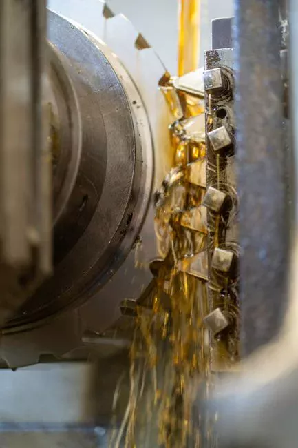
Spent machining coolant blowdown from CNC and grinding operations is an emulsified oil wastewater stream that municipal MBRs were never designed to handle, and the failure mode is fast: a flat-sheet MBR fed raw coolant will lose 60-80% of its flux within 48-72 hours. The feed is a stable oil-in-water emulsion at 3-10% mineral or semi-synthetic oil, loaded with anionic and non-ionic surfactants, isothiazolinone or triazine biocides, ethylene glycol, and episodic tramp oil from hydraulic leaks that pushes free-oil spikes above 1,000 mg/L during machine failures. This composition breaks an MBR in three simultaneous ways.
First, emulsified oil droplets in the 0.1-10 µm range physically blind 0.1-0.4 µm membrane pores (per Oklahoma DEQ WQD-002, the nominal microfiltration band MBRs operate in), and the smaller the pore the worse the blinding. Second, the surfactants that keep the emulsion stable in the sump also defoam the activated-sludge aeration basin, collapsing the MLSS floc structure and crashing mixed-liquus settleability before the water ever reaches the membrane cassette. Third, the raw COD/BOD of spent coolant runs 5,000-25,000 mg/L — well above the 800-1,500 mg/L feed that activated-sludge biology is designed to metabolize — so the biology is substrate-inhibited before degradation begins.
More than 5,000 MBR plants now operate worldwide, the vast majority municipal (MDPI 2026 MBR review, 2026-05), and their design envelope does not include emulsified oil. A municipal-spec MBR with no oil protection will foul in days; an industrial-spec MBR with the right configuration and a working pretreatment train runs 6-12 months between clean-in-place cycles. That gap is the entire reason configuration and pretreatment choice matter for any metalworking fluid treatment project evaluating membrane bioreactor technology.
The Three MBR Configurations That Can Handle Oily Industrial Feed
Three submerged membrane bioreactor geometries are bid-specifiable for coolant service: submerged flat-sheet, submerged hollow-fiber, and sidestream cross-flow. They differ sharply on oil tolerance, energy, and cleanability, and the difference is what determines whether the system runs a year between cleanings or fails weekly.
Submerged flat-sheet modules — the DF series style geometry — use 0.1 µm PVDF panels mounted in a cassette and scoured by coarse-bubble aeration from an integrated air box below the cassette. The flat geometry tolerates suspended solids and oil droplets that would mat hollow fibers together, and the sheets can be backwashed and physically wiped during recovery cleans. Specific energy demand runs 0.1-0.3 kWh/m³ of permeate, roughly an order of magnitude below sidestream cross-flow at comparable flux (HydropureWater DF series data, 2026). This geometry is the default choice for coolant blowdown in a packaged DF series flat-sheet PVDF MBR module or a skid-mounted integrated MBR wastewater treatment system.
Submerged hollow-fiber modules cost less per square meter of membrane area and pack more area into a smaller cassette, but the geometry is the wrong shape for oily feed. Fibers mat against each other; oil wicks along the fiber bundle and is almost impossible to remove by backwash alone. Field studies on emulsified industrial feed report irreversible fouling within weeks when oil-into-MBR is not held below 10-15 mg/L. Sidestream cross-flow loops generate high shear at the membrane surface and tolerate very high MLSS or temperatures above 40 °C, but they consume 1-3 kWh/m³, roughly 10× the submerged flat-sheet baseline. Sidestream is justified only when the biology must run hot or very concentrated.
| Parameter | Submerged flat-sheet (PVDF) | Submerged hollow-fiber | Sidestream cross-flow |
|---|---|---|---|
| Nominal pore size | 0.1 µm (tighter end of 0.1-0.4 µm MBR range, per Oklahoma DEQ WQD-002) | 0.1-0.4 µm | 0.1-0.4 µm |
| Oil tolerance into MBR | Up to ~25 mg/L with flat-sheet scour | <10-15 mg/L before irreversible fouling | 50-100 mg/L at high cross-flow velocity |
| MLSS operating range | 8,000-12,000 mg/L | 6,000-10,000 mg/L | 15,000-25,000 mg/L |
| Footprint (per m³/d) | Moderate (cassette area) | Small (high packing density) | Small (loop external to tank) |
| Specific energy | 0.1-0.3 kWh/m³ | 0.2-0.4 kWh/m³ | 1-3 kWh/m³ |
| Typical CIP frequency (coolant service) | 6-12 months | 2-6 weeks on oily feed | 1-3 months |
| Capital cost index (relative) | 1.0× | 0.8-0.9× | 1.4-1.8× |
For emulsified metalworking fluid treatment, the table makes the trade-off explicit: flat-sheet costs more upfront than hollow-fiber but survives oily feed 5-10× longer between cleanings, which dominates lifecycle cost in real coolant service.
Pretreatment Train Before the MBR: Oil Removal Is Not Optional
An MBR is a solids-separation device, not an oil-removal device. Feeding emulsified coolant directly to a submerged membrane bioreactor is the single most common reason industrial MBRs fail on metalworking wastewater. The pretreatment train in front of the MBR has four jobs: drop free oil to under 100 mg/L, drop emulsified oil to under 25 mg/L, equalize flow and pH, and neutralize biocide toxicity before the biomass is exposed.
- Oil/water separator or coalescer. First stage, removes free and tramp oil from hydraulic leaks. A correctly sized corrugated-plate coalescer typically drops total oil from 1,000-5,000 mg/L at the sump to under 100 mg/L. This protects transfer pumps and the equalization tank from oil fouling and reduces the load on DAF chemistry.
- Dissolved air flotation (DAF) with coagulant and flocculant. The center of the train. A chemical coagulation step (typically aluminum or ferric-based coagulant at 50-150 mg/L, paired with an anionic or cationic flocculant at 1-5 mg/L) destabilizes the emulsion; the DAF then floats the destabilized oil and TSS in a white sludge blanket. Properly operated, a dissolved air flotation system drops total oil to under 25 mg/L and TSS to under 50 mg/L ahead of the MBR, in capacities from 4 m³/h up to 300 m³/h per unit (HydropureWater DAF product data, 2026). The same pretreatment pattern used on stamping press oily water pretreatment before DAF applies to coolant blowdown because the upstream oil-removal physics are identical.
- Equalization basin with pH and nutrient control. Spent coolant emulsions typically run pH 8.5-10 from amine-based corrosion inhibitors; pH must be adjusted to 6.5-8.0 for downstream biology. Nitrogen and phosphorus are often deficient relative to the carbon load, so urea or ammonium salts and phosphoric acid are dosed to hold a BOD:N:P ratio around 100:5:1. An automatic chemical dosing system on pH and ORP loops keeps the equalized feed consistent, which is what makes the downstream MBR biology stable.
- Biocide neutralization (selective). Isothiazolinone-based coolant additives are biocidal by design and will kill MLSS within hours. Options include activated-carbon adsorption, reducing-agent dosing (sodium bisulfite), or — where the plant can reformulate — switching the coolant to a biocide-free or lower-toxicity package. Comparable wash-water feeds from die-cast aluminum wash water pretreatment before DAF have the same issue with residual surfactants and need the same neutralization step.
Membrane Selection and Operating Parameters for Coolant Service
Configuration choice translates into specific operating numbers the design engineer has to lock in before commissioning. For emulsified coolant blowdown, the envelope is narrower than for municipal MBR service and leaves less room for error.
Membrane specification should be 0.1 µm PVDF flat-sheet, the tight end of the 0.1-0.4 µm microfiltration band (per Oklahoma DEQ WQD-002) chosen specifically to physically reject emulsified oil droplets in the 0.5-5 µm range. PVDF is preferred over PES or PS for chemical resistance to the glycols, amines, and pH excursions typical of coolant sumps. MLSS should be held at 8,000-12,000 mg/L. Below 8,000 mg/L, biology cannot keep up with the COD load; above 15,000 mg/L, mixed-liquor viscosity rises and the coarse-bubble scour beneath the flat-sheet cassette loses effectiveness, accelerating fouling.
Solids retention time (SRT) should run 30-60 days — long enough to retain the slow-growing bacteria that biodegrade the resistant non-ionic surfactants and glycols in semi-synthetic coolants. Hydraulic retention time (HRT) is typically 12-36 hours depending on feed strength. Flux on flat-sheet submerged MBRs should be set at 10-18 LMH for coolant service; if oil-into-MBR rises above 25 mg/L due to a DAF upset, derate flux to 8-12 LMH to slow membrane fouling until the upstream recovers. Aeration intensity at the cassette should be 0.2-0.4 m³ of air per m² of membrane area per minute — enough to scour the sheet surface without over-stripping CO₂ from the biology.
Reuse Targets and Discharge Limits Side by Side
Whether the MBR effluent goes to sewer or back into the coolant make-up tank sets the operating target, and the targets are different enough that the design has to be biased toward the stricter of the two. In practice, designing for reuse is the most economically defensible 2026 pathway when POTW surcharges are rising.
| Parameter | NPDES metal finishing benchmark (40 CFR Part 433) | Reuse as coolant make-up (target) |
|---|---|---|
| COD | Report per metal-finishing category (verify current 40 CFR Part 433 limits for your subcategory) | < 50 mg/L |
| BOD₅ | Report per 40 CFR Part 433 | < 10 mg/L |
| TSS | Report per 40 CFR Part 433 | < 5 mg/L |
| Oil & grease | Report per 40 CFR Part 433 | < 5 mg/L |
| Conductivity | Not typically regulated | Controlled by partial blend with fresh water and virgin concentrate (typically 200-800 µS/cm in the make-up tank) |
| pH | 6.0-9.0 standard range | 8.5-9.5 (matches virgin coolant concentrate window) |
| Hardness (as CaCO₃) | Not typically regulated | < 50 mg/L to avoid scum and tool deposits |
Operators should confirm current 40 CFR Part 433 numerical limits for their specific metal-finishing subcategory before specifying, as the federal rule sets category-by-category reporting and compliance values. For internal water reuse in manufacturing, the coolant make-up target is the binding constraint: COD under 50 mg/L, TSS under 5 mg/L, and oil under 5 mg/L are the parameters the MBR must hit. Hardness and conductivity are not regulated for discharge but matter for reuse, because high hardness forms scum in the sump and high conductivity accelerates tool corrosion.
The most defensible 2026 operating mode is partial reuse at 10-30% blowdown-to-make-up substitution, blended with fresh water and virgin concentrate to stay inside the make-up tank's water-quality window. This route captures most of the water-saving benefit, limits the risk of trace contaminants building up in the coolant sump, and avoids the full-zero-liquid-discharge complexity of RO polishing. Where cooling-tower-style reuse is also in play, the same RO-polishing approach used for cooling tower blowdown reuse with RO can be added downstream of the MBR as a second stage for plants aiming at higher substitution rates.
Frequently Asked Questions
Which MBR configuration is most common for machining coolant blowdown?
Submerged flat-sheet PVDF at 0.1 µm pore size is the default geometry for emulsified coolant service because the flat panel tolerates oil droplets and can be backwashed and physically wiped, whereas hollow-fiber bundles mat irreversibly on oily feed within weeks (HydropureWater field data, 2026).
What oil level is acceptable into the MBR?
Total oil should be under 25 mg/L entering the MBR cassette for flat-sheet systems, derating flux to 8-12 LMH; for hollow-fiber, the limit is closer to 10-15 mg/L before irreversible fouling sets in. This is why DAF pretreatment is non-negotiable.
Can MBR effluent be reused as coolant make-up water?
Yes, when the MBR is sized and operated to hit COD < 50 mg/L, TSS < 5 mg/L, and oil < 5 mg/L; the effluent is typically blended at 10-30% with fresh water and virgin concentrate to control hardness and conductivity in the make-up tank.
How often do MBR membranes need chemical cleaning on coolant service?
A well-pretreated flat-sheet MBR on coolant blowdown runs 6-12 months between clean-in-place cycles, compared to 2-6 weeks for a hollow-fiber system on the same feed without adequate oil removal upstream. CIP interval is the single best indicator of whether pretreatment is working.
What size MBR is typical for a 50-machine CNC shop?
A 50-machine shop generating 30-80 m³/d of coolant blowdown typically pairs a 50-100 m³/d MBR with a 10-30 m³/h DAF, equalization for 24 hours of flow, and an automatic chemical dosing system on pH and flocculant — packaged as a skid-mounted system to minimize install time on a crowded shop floor.