
What Makes Stamping Press Oily Water Different from Refinery or Food Oil Wastewater
Stamping press effluent is a four-phase mixture containing contaminants not found in refinery desalters or food-oil plants: free tramp oil from the die, water-soluble and semi-synthetic drawing compounds, suspended metal fines (iron swarf, aluminum, and zinc), and intermittent hydraulic fluid from press leaks. Oil and grease concentrations routinely swing from 200 to 5,000 mg/L between heavy draw operations and lighter overnight blank-and-trim cells, whereas refinery desalter water typically holds a tighter 500–1,500 mg/L band (S2, S3).
The free-versus-emulsified split dictates equipment selection. Stamping wastewater is typically 40–70% free oil by mass, making a skimmer essential upstream of chemical treatment. Food-oil effluent is mostly emulsified and benefits less from physical separation; refinery desalter water is hot, saline, and chemically reduced, which alters floc chemistry. Stamping water remains at ambient temperature and near-neutral pH, containing an oxidizable metal-fine fraction that consumes dissolved oxygen in holding basins.
The hydraulic profile is similarly volatile. Press shops operate intermittently: a tonnage cycle floods the floor drain during the draw, followed by minutes of inactivity during part transfer. Weekend washdowns push slugs of alkaline cleaner (pH 10–12) through the same drain, and a single hydraulic line rupture can deliver 50–200 L of mineral oil in minutes. Field data from press-shop ETPs (HydropureWater, 2024–2025 retrofits) show hourly flow variation factors of 3–6× average and oil-concentration peaks of 5–8× average, confirming that equalization is a mandatory step for stable DAF performance (S4, MDPI Processes 2020).
Why DAF Needs Pretreatment: Failure Modes When You Skip It
A DAF unit rated for 90–95% oil removal on a stable refinery feed will drop below 60% removal on raw stamping water due to mechanical failure. Micro-bubbles generated at 4–6 bar saturator pressure are 10–80 µm in diameter and have a finite oil-carrying capacity. When free oil entering the flotation cell exceeds roughly 100 mg/L, the bubble surface saturates with oil film, attachment efficiency for oil-coated floc particles collapses, and bubbles slip through the sludge blanket carrying little payload (S2, S3, S4).
Hydraulic failure is the second primary risk. A DAF cell skims the top 0.5–1.0 m as float; if the incoming oil load is high, the float layer re-entrains at the launder weir and appears as a visible sheen on the clarified water. Operators attempting to fix this with more polymer often make it worse, as overdosed polymer carries oil back into the bulk rather than out the top. Skimmer carry-over is the most common reason DAF discharge fails the 10–15 mg/L oil and grease limit on automotive stamping lines.
Mechanical failure is the third risk. Stamping fines at 50–500 mg/L TSS—mostly iron and aluminum in the 20–200 µm range—lodge in DAF nozzle headers, plug race-track orifices in the recycle distribution system, and erode the saturator pump. Without upstream screening, the DAF recycle pump fails first, the cell goes anaerobic second, and the discharge fails third. These modes cannot be fixed by tuning the DAF itself, which is why the pretreatment train is designed to prevent them.
Finally, pH drift from alkaline washdown slugs pushes the coagulation window outside the 6.5–8.0 range where PAC and anionic polyacrylamide are effective. A DAF fed at pH 9.5 produces a loose, low-density floc that does not attach to bubbles, leaving the cell effluent turbid for hours after a single washdown event.
The Five-Step Pretreatment Train for Stamping Press Oily Water
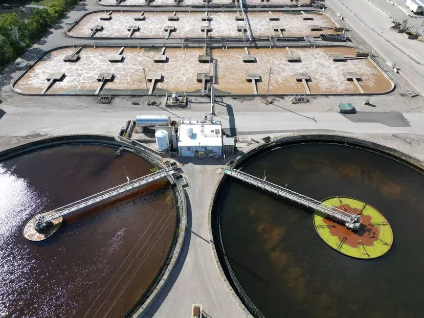
The pretreatment sequence is designed so each step solves a specific problem the next step cannot handle.
Step 1 — Coarse screening. A rotary mechanical bar screen with 2–5 mm openings sits at the headworks to capture metal swarf, rag wipers, cardboard, and dropped workpieces. Sizing is based on peak instantaneous flow rather than average, as press shops flood during cycle drains. A GX series rotary mechanical bar screen sized to 1.5× peak hourly flow protects downstream transfer pumps, equalization basin mixers, and the DAF recycle pump. A differential-pressure trip at 0.3–0.5 m water column alarms the operator, while higher trips trigger a bypass to prevent upstream flooding.
Step 2 — Free-oil skimming. An inclined-plate or rotary drum skimmer pulls the free oil layer down to a residual below 50 mg/L. This step must precede coagulant addition because free oil consumes PAC and anionic polymer on contact; the same 100 mg/L of free oil that hinders DAF also burns 20–40 mg/L of coagulant dose and shifts the polymer optimum by a factor of two. Skimmer surface loading is typically held at 10–20 m³/m²·h to allow free oil to coalesce on the plate pack.
Step 3 — Equalization. An 8–24 hour HRT basin with diffused or mechanical aeration damps flow and concentration swings. Aeration is necessary for stamping water because the emulsified oil fraction and sulfite-bearing drawing compounds strip dissolved oxygen and can turn the basin septic within hours. A correctly sized EQ basin reduces hourly oil-concentration peaks from 5–8× average to within ±20% of the daily mean, providing the stability a DAF requires.
Step 4 — pH adjustment. Sulfuric acid (typical 93% technical grade) or CO₂ is dosed to maintain a pH of 6.5–8.0, with a control deadband of ±0.3. This window is narrow because alum and polyaluminum chloride (PAC) lose charge below pH 6 and form soluble aluminum species above pH 8; anionic polyacrylamide requires a pH above 6.5 to maintain the negative backbone charge that attracts cationic floc. Inline pH probes feed back to the automatic chemical dosing skid through a PLC trim loop.
Step 5 — Coagulation–flocculation. Rapid mix (G ≈ 300–500 s⁻¹, 30–60 s) with PAC at 50–150 mg/L is followed by slow mix (G ≈ 50–80 s⁻¹, 3–5 min) with anionic polyacrylamide at 1–5 mg/L. The floc must mature for 3–5 minutes in a dedicated flocculation zone before reaching the DAF inlet to prevent the floc from shattering at the saturator shear point. A PLC-locked polymer activation tank (30–60 min maturation of the neat emulsion before dilution) is included in the dosing skid scope.
| Step | Unit Operation | Design Parameter | Operating Window |
|---|---|---|---|
| 1 | Coarse screening | Bar screen opening | 2–5 mm |
| 2 | Free-oil skimming | Residual free oil after skimmer | <50 mg/L |
| 3 | Equalization basin | HRT | 8–24 h |
| 4 | pH adjustment | Setpoint | 6.5–8.0 (±0.3) |
| 5a | Rapid mix / coagulation | PAC dose | 50–150 mg/L |
| 5b | Slow mix / flocculation | Anionic polymer dose | 1–5 mg/L |
| 5c | Floc maturation | Residence time before DAF | 3–5 min |
Design Parameters and Operating Windows for Each Pretreatment Step
Equalization volume calculations determine whether the DAF can be operated at a single setpoint. The arithmetic is: V_EQ = Q_peak × t_peak − Q_avg × t_avg, summed over one full press-shift cycle. For a typical automotive stamping line consuming 4–8 L of water per ton of stamped part, with 80–120 t/shift on two shifts and a peak factor of 3× average, the working volume is 80–250 m³, plus freeboard for washdown slugs. Mechanical aeration at 0.5–1.0 m³ air per m³ water per hour keeps DO above 1.5 mg/L in an actively mixed EQ basin.
Polymer activation is another critical design factor. Anionic polyacrylamide emulsions arrive at 25–50% active and must be aged in a low-shear maturation tank for 30–60 minutes before make-down water dilutes them to working strength (0.05–0.2%). Skipping aging or using high shear reduces the effective molecular weight and ruins the floc. A dosing skid with a dedicated aging tank and two-stage dilution provides a repeatable setpoint rather than three variables for the operator to manage.
The entire train must be sized to the same hydraulic envelope as the DAF to prevent bottlenecks. The dissolved air flotation system covers 4–300 m³/h; if EQ basin pumps and the screen channel are sized to 200 m³/h while the DAF is a 300 m³/h cell, the EQ will throttle the train and the DAF will run starved. The pretreatment envelope must match the DAF envelope exactly, with a 10–15% hydraulic margin for polymer dilution water and skimmer oil discharge.
Commissioning Checklist: Verifying Your Pretreatment Train Before DAF Startup
Perform these four tests on the upstream train before energizing the DAF.
- Jar test to lock coagulant and polymer dose. Sample raw effluent post-skimmer, dose PAC at 50, 75, 100, 125, 150 mg/L and anionic polymer at 1, 2, 3, 5 mg/L on a six-paddle gang stirrer. Lock the dose pair that gives the clearest supernatant at 5 minutes settling and record residual oil by hexane extraction to set the dosing skid. >
- 24-hour equalization profile. Sample the EQ basin influent and effluent every two hours over one full production day and one washdown event. Confirm effluent oil and pH both vary by less than ±20% from the daily mean. If pH swings exceed 0.5 units, add a pH trim loop at the EQ outlet rather than the DAF inlet.
- Skimmer performance verification. Grab-sample the skimmer effluent three times per shift for the first week. Hexane extraction should return free oil below 50 mg/L. An in-line oil-in-water sensor (UV fluorescence or scattered-light) at the skimmer discharge provides continuous confirmation for the trend log.
- Screen differential-pressure test. Force a partial blinding of the GX series rotary mechanical bar screen by feeding rags into the upstream channel. Verify the high-dP alarm fires at 0.3–0.5 m water column and the bypass interlock opens at 0.7 m before starting the DAF recycle pump.
Frequently Asked Questions
Do I really need a skimmer if I have a DAF? Yes. Free oil above 50–100 mg/L coats DAF micro-bubbles and drops oil removal below 60%; a skimmer to <50 mg/L residual protects the bubble surface and typically reduces PAC dose by 20–40 mg/L. Skim first, then float.
What is the right pH for coagulation before DAF on stamping water? Hold 6.5–8.0 with a ±0.3 deadband. Below 6.0, PAC loses cationic charge