What an E-Coat UF Reject Stream Actually Contains
E-coat ultrafiltration reject is the 5–15% concentrate bleed pulled from a closed-loop UF circuit wrapped around a cathodic electrodeposition (CED) tank. UF permeate returns to the final rinse; the concentrate leaves the loop carrying everything too large to pass the 5–20 kDa UF membrane — solubilized resin, glycol ethers, pigment fines, and surfactant drag-in from the bath. Designers who skip characterization of this bleed default to municipal-grade assumptions and overspend on biology that cannot work.
Typical reject composition at a tier-1 automotive coater runs 500–5,000 mg/L COD (of which less than 10% is biodegradable — the rest is resin and glycol ether), 200–2,000 mg/L TSS (pigment and resin particles), TDS 1,000–8,000 mg/L, pH 5.5–6.5, and temperature 30–40 °C. Low-ppb lead, tin, and surfactant residues are common. The BOD:COD ratio sits below 0.1, which is the critical number: conventional activated sludge cannot hold biomass long enough to acclimate to the refractory fraction because HRT and SRT are coupled in a clarifier.
A membrane is mandatory to manage these refractory loads. The membrane decouples hydraulic retention time (HRT) from solids retention time (SRT), letting the operator run a 30–60 day SRT inside a 6–12 h reactor — a configuration the membrane bioreactor literature has validated for low-BOD industrial streams for over three decades (Frontiers in Membrane Science, 2024). Without that decoupling, biology washes out and the system fails on day one.
Submerged Flat-Sheet vs Sidestream Tubular: Which MBR Configuration Wins
A submerged flat-sheet PVDF MBR with 0.1 μm nominal pore size is the baseline configuration for e-coat UF reject. It handles the 30–40 °C feed, tolerates 200–500 mg/L pigment TSS in the equalized stream, and — because aeration is integrated under the cassette — consumes roughly 10–20× less energy than a sidestream tubular (cross-flow) design at the same daily throughput. The DF-series 0.1 μm PVDF flat-sheet MBR module is the default hardware referenced in paint-shop MBR specifications for 2026.
Sidestream tubular MBR is reserved for two edge cases. (1) Pigment breakthrough above 200 mg/L after a DAF system for paint solids pre-removal, where high cross-flow velocity scours particles that would blind a flat-sheet cassette. (2) Solvent breakthrough in the reject — usually from a degreaser leak upstream — that would compact a flat-sheet membrane; tubular stainless or PVDF modules tolerate the solvent and run at higher TMP.
Hollow-fiber MBR is generally avoided on e-coat reject. Pigment and resin foul the inside of the fibers irreversibly, and a single broken fiber contaminates the entire permeate. Flat-sheet cassettes are individually replaceable, which matters for a continuous paint line that cannot accept a full-train shutdown. Anaerobic MBR is also excluded: the carbon source is too refractory, and the residence time needed exceeds 5 days at 35 °C, which is uneconomical compared with aerobic submerged operation. Aerobic submerged MBR is the established configuration for low-BOD industrial streams (Membranes, 2021; Water, 2014).
| Parameter | Submerged Flat-Sheet PVDF | Sidestream Tubular |
|---|---|---|
| Best feed TSS | 200–500 mg/L | 500–2,000 mg/L |
| Temperature ceiling | 40 °C | 45 °C (stainless) |
| Energy use (kWh/m³) | 0.3–0.6 | 3–8 |
| Solvent tolerance | Low | Moderate–high |
| Membrane replacement | Per cassette, hours | Per module, shift |
| Default for e-coat reject? | Yes | Edge cases only |
Operating Window: MLSS, Flux, SRT, and TMP for E-Coat Reject
MLSS runs 8,000–12,000 mg/L — higher than the 6,000–8,000 mg/L typical of municipal MBR — to compensate for the low BOD:COD ratio and keep biomass in contact with the refractory COD long enough to oxidize the biodegradable fraction. Sustained MLSS above 12,000 mg/L starts to hurt oxygen transfer and viscosity.
Design flux is 15 LMH; the operating range is 10–25 LMH at 0.1 μm pore size per the DF-series specification. SRT runs 30–60 days; HRT runs 6–12 h. Long SRT is the reason MBR beats conventional activated sludge on this stream: the biology is given enough time to acclimate to the resin and surfactant fraction. TMP ceiling is 0.3 bar; chemical-in-place cleaning every 6–10 weeks with 1,000 mg/L NaOCl is the standard maintenance interval.
Temperature ceiling is 40 °C sustained. Above that, polymeric flat-sheet modules lose integrity and a sidestream tubular stainless configuration becomes mandatory. DO is held at 2–4 mg/L via continuous coarse-bubble aeration under the cassette — the airlift both oxygenates the mixed liquor and scours the membrane surface, which keeps flat-sheet MBR online between CIP cycles.
| Parameter | Operating Range | Design Point | Note |
|---|---|---|---|
| MLSS (mg/L) | 8,000–12,000 | 10,000 | Higher than municipal to offset low BOD:COD |
| Flux (LMH) | 10–25 | 15 | 0.1 μm PVDF, 25 °C reference |
| SRT (days) | 30–60 | 45 | Decoupled from HRT by membrane |
| HRT (h) | 6–12 | 8 | Equalized feed, 35 °C |
| TMP ceiling (bar) | ≤ 0.3 | 0.2 | CIP at 6–10 weeks |
| Temperature (°C) | ≤ 40 | 35 | Plate heat exchanger if bath > 40 °C |
| DO (mg/L) | 2–4 | 3 | Coarse-bubble under cassette |
Reuse vs Discharge: When the MBR Stands Alone vs When It Feeds RO
MBR alone is sufficient for indirect discharge to a POTW. MBR permeate from the operating window above delivers COD < 50 mg/L, TSS < 5 mg/L, and lead < 0.5 mg/L — numbers that meet most US POTW discharge limits and the EU Industrial Emissions Directive thresholds for automotive paint wastewater. An integrated MBR wastewater treatment system sized to the design point above is a complete discharge package in this mode.
MBR + RO is the reuse train. RO polish with antiscalant and pH adjustment brings TDS below 50 mg/L, suitable for return to the e-coat final rinse or the deionized rinse loop. Recovery of 75–85% is realistic on this stream; the Frontiers 2024 review of MBR+NF/RO hybrid systems reports 84% recovery as a representative operating point for low-BOD industrial feeds. An industrial RO system for MBR permeate polish is the standard second stage.
Where water tariffs exceed roughly USD 4/m³ — or where the plant sits inside a ZLD-mandated cluster per the related guide on ZLD mandate clusters in India and China — the train extends to MBR + RO + concentrate evaporation. RO concentrate from e-coat reject is typically sent to the plant's existing FGD scrubber or a small brine concentrator, not to a hard crystallizer, because the volume is small and the dissolved solids are compatible with those sinks. If the goal is POTW compliance, stop at MBR; if the goal is rinse-water reuse or a ZLD loop, add RO.
Pretreatment and Equalization Before the MBR Cassette
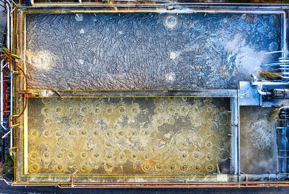
Most MBR failures on e-coat reject result from inadequate equalization upstream rather than membrane selection. The UF loop dumps 3× swings in TDS and pH during bath top-up and DI rinse cycles; those swings hit the cassette before the biology can buffer them. Size equalization at 12–24 h of UF reject flow as a starting point, then verify against the actual dump frequency of the CED bath.
pH trim to 6.5–7.5 via NaOH dosing is mandatory; outside that band, PVDF membrane lifetime shortens and nitrifier activity collapses. Cooling to below 38 °C with a plate heat exchanger is required if the e-coat bath runs above 40 °C, which is common at plants that skip bath-temperature trim. Coarse screening at 1–2 mm protects the cassette from agglomerated resin and any rag or wipe that escapes the upstream booth. A DAF system for paint solids pre-removal in front of the MBR is the most effective guard against a 2,000 mg/L TSS spike blinding the flat-sheet cassette in under two hours. The related guide on paint-booth curtain water pretreatment before MBR covers the upstream DAF and screening logic in more detail for plants co-treating booth water with the e-coat stream.
Frequently Asked Questions
What MBR configuration treats e-coat UF reject for reuse or discharge?
A submerged flat-sheet PVDF MBR with 0.1 μm pore size, 8,000–12,000 mg/L MLSS, and 30–60 day SRT is the default; it produces permeate that meets POTW limits directly or feeds an RO polish for rinse-water reuse at 75–85% recovery.
Why is sidestream tubular MBR not the default for e-coat reject?
Sidestream tubular MBR consumes 10–20× more energy than submerged flat-sheet and is only justified when pigment loading exceeds 200 mg/L after DAF or when organic solvent breakthrough is present in the reject stream.
Can hollow-fiber MBR be used on e-coat UF reject?
Hollow-fiber MBR is generally avoided because pigment and resin foul the inside of the fibers irreversibly; flat-sheet cassettes allow individual replacement without shutting the paint line down.
When does the MBR need an RO stage downstream?
Whenever the goal is rinse-