Why Raw HF Etch Waste Destroys an MBBR Biofilm
A biofilm dies in an MBBR long before the operators notice the failure. Free fluoride above 20-30 mg/L collapses nitrifier activity within 2-6 hours, heterotroph die-off follows within 12-24 hours, and the carrier surface is left fouled with CaF2 and SiO2 scale that physically blocks recolonization (per Kaldnes K1 baseline media performance, Tanjungpura University 2018 MBBR study, doi:10.26418/jtllb.v7i1.31882). Three independent kill mechanisms fire at once: (1) pH shock at pH <2 lyses the extracellular polymeric substance layer that holds the biofilm to the polyethylene carrier; (2) free F⁻ inhibits enolase and H+-ATPase in nitrifying bacteria at concentrations as low as 10 mg/L, halting ammonia oxidation first; (3) CaF2 (Ksp ~3.9×10⁻11) and amorphous SiO2 precipitate on the carrier and inside the media pockets, blinding surface area and adding 5-15 kg of inorganic mass per m³ of reactor volume. The combination is unrecoverable without carrier removal and acid wash.
Raw HF etch waste hits the MBBR with pH 1-3, free F⁻ 500-5,000 mg/L, dissolved silica 50-300 mg/L as SiO2, and H2SiF6 / NH4F complexes from buffered oxide etch (BOE) mixes. COD sits at 200-1,500 mg/L from organic strippers, surfactants, and IPA residues carried over from the etch bath dumps. That fingerprint is roughly two orders of magnitude outside the MBBR operating envelope of pH 6.5-8.5, 10-35 °C, and free F⁻ ≤20-30 mg/L, so direct feed is not a process option. The only safe path is the staged pretreatment train: equalization → two-stage pH correction → fluoride precipitation → Fenton/coagulation → dissolved air flotation (DAF) system → multimedia filter, then the MBBR feed sump.
MBBR Feed Specification HF Etch Waste Must Hit
The MBBR influent envelope is the design contract. Anything outside it either kills the biofilm or pushes the system into a fouling steady state that cannot be recovered without taking the reactor offline. Use this as the procurement specification and the P&ID feed-limit table.
| Parameter | MBBR Feed Limit | Notes |
|---|---|---|
| pH | 6.5-8.5 | Hard interlock; divert if outside range |
| Free F⁻ | ≤15 mg/L | Ion-selective probe measurement |
| Total F⁻ | ≤30 mg/L | Acceptable if complexed with Al, Ca, or Fe |
| COD | ≤1,000 mg/L | Fenton required above 800-1,000 mg/L |
| BOD/COD | ≥0.3 | Below 0.25 indicates non-biodegradable load |
| TSS | ≤80 mg/L | DAF + multimedia target <30 mg/L |
| Temperature | 15-30 °C | Below 10 °C nitrification rate halves |
| Salinity | <8 g/L as Cl⁻ | Higher Cl⁻ inhibits Nitrosomonas |
| Oil & grease | None detectable | Coats carriers and blocks O2 transfer |
| Ca hardness | Coordinate with nutrient dosing | Residual Ca²⁺ >800 mg/L scales carriers |
Free F⁻ is the controlling variable, not total F⁻. Fluoride complexed with Al³⁺, Si⁴⁺, Ca²⁺, or Fe³⁺ is largely non-bioavailable because the F⁻ is locked in a sparingly soluble lattice; a 30 mg/L total F⁻ reading with all F bound to Al(OH)3 floc is a safer MBBR feed than a 20 mg/L total F⁻ reading with most of the F as free ionic F⁻ at pH 7. Confirm with an ion-selective electrode (ISE) calibrated against TISAB buffer, not just an SPADNS colorimetric total F⁻. Exceeding any single parameter means reverting flow to the upstream pretreatment step, not pushing more air or higher recirculation into the MBBR. "Running the MBBR harder" is how carriers get permanently fouled.
Stage 1: Equalization and Two-Stage pH Correction
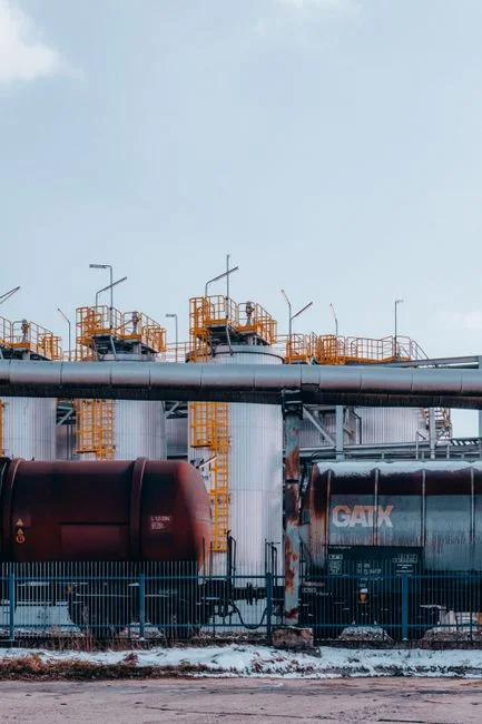
Equalization smooths the dump cycle so the downstream chemistry has a stable feed. Target a 12-24 h hydraulic residence time (HRT) in a FRP or dual-laminate PP tank with mechanical or jet mixing sized to hold pH variation across the EQ outlet to <1 unit. On a fab or panel plant with multiple etch tools, the F⁻ loading can swing 3-5× between shifts; without EQ the dosing system chases setpoint and under-doses on the peak dumps. EQ also buffers the volatile HF off-gassing risk: at pH <2 with active airflow through an uncovered tank, HF vapor can reach 5-20 mg/m³ at the tank rim, which is above the OSHA PEL-TWA of 2.5 mg/m³ as F. Keep the EQ covered and vent through a packed scrubber.
Two-stage pH correction exists because a single lime or caustic shot fails on spent HF. Stage A lifts to pH 4-5 in a 15-20 min stirred reactor with NaOH (10-20% w/w) or Ca(OH)2 slurry; this converts the residual HF to F⁻ without driving local pH >10 hot spots that would precipitate Ca(OH)2 instead of the CaF2 you actually want in the next stage. Stage B trims to pH 7.0-8.0 in an in-line static mixer or second CSTR with NaOH, where the residence time is short and the control loop is tight. A single-stage dump to pH 7-8 generates local pH >11 zones near the dosing point, produces fine Ca(OH)2 particles that pass straight through to the MBBR, and wastes 20-40% of the alkali on unreacted base. Specify EPDM or PTFE-lined agitators, Hastelloy C-276 or PVDF dosing heads, and FRP or dual-laminate tanks; 316L stainless is not acceptable above 1,000 mg/L F⁻ at low pH. The automatic chemical dosing system should run pH feedback on Stage B with a redundant probe, since a pH probe failure mid-shift is the most common cause of pH excursions into the MBBR.
Stage 2: Fluoride Precipitation With Calcium or Aluminum
Fluoride precipitation is the unit operation that does the actual work of making the water MBBR-safe. The primary reaction is 2 F⁻ + Ca²⁺ → CaF2 (Ksp ~3.9×10⁻11), and the stoichiometric Ca:F molar ratio is 1:1. In practice, design at 2:1 to push residual F⁻ reliably below 15 mg/L, and account for competing reactions with silica, phosphate, and carbonate that consume Ca²⁺ without removing F⁻. For a 1,000 mg/L F⁻ influent at 2:1 Ca:F, dose 6-10 g/L as Ca(OH)2 for lime or 8-12 g/L as CaCl2·2H2O for calcium chloride; expect 85-95% F⁻ removal to a residual of 5-15 mg/L with 30-60 min HRT at slow mixing 20-40 rpm to keep the CaF2 crystals growing rather than fragmenting into fines that escape the clarifier.
Lime is cheaper per kg of Ca²⁺ and co-precipitates silica, heavy metals, and residual phosphate, but it raises sludge volume 30-50% and can foul downstream piping with CaCO3 if the clarifier effluent picks up CO2 from the air. CaCl2 is the cleaner option: less sludge, no CaCO3 fouling, and easier pH trim because chloride does not consume acid. Aluminum coagulation is the alternative when residual F⁻ must drop to 5-10 mg/L and the silica load is high; dose polyaluminum chloride (PAC) or alum at 100-300 mg/L as Al at pH 6-7. PAC produces a more gelatinous, harder-to-dewater sludge than CaF2 and is more pH-sensitive, so the operating window is narrower. For fab and panel etch waste with 50-300 mg/L SiO2 and F⁻ >1,000 mg/L, a Ca-primary followed by PAC-polish is the typical high-removal configuration.
Watch the residual Ca²⁺ on the MBBR feed line. Over-stoichiometric Ca pushes residual Ca²⁺ above 800 mg/L, which then precipitates as CaCO3 and CaF2 on the carrier surface once the MBBR pH drifts up to 8.0-8.3. Design the Ca dose against the F⁻ residual target, not against "more is safer"; a F⁻ ion-selective probe on the reactor outlet is the right control loop, not a flow-proportional Ca feed. Send the CaF2 sludge to a thickener (4-6 h HRT) and then a filter press for dewatering; expect 18-25% dry solids in the cake and a CaF2 purity of 60-80%, which can be diverted to cement kiln feedstock or hazardous landfill depending on the co-precipitated metal content.
Stage 3: Fenton Oxidation for High-COD Etch Streams
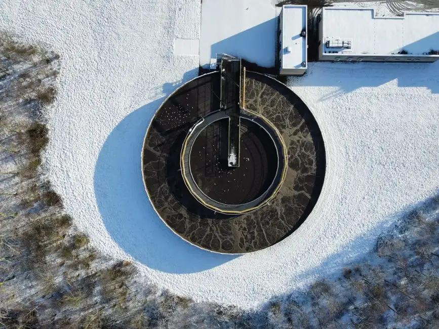
Fenton is a targeted step, not a default. Trigger Fenton when the MBBR feed COD would exceed 800-1,000 mg/L or when the BOD/COD ratio is below 0.25, which signals that the organic load is dominated by non-biodegradable strippers, surfactants, glycol ethers, and NMP residues from the etch line rather than biodegradable BOD. Pushing non-biodegradable COD at 1,500-2,000 mg/L into the MBBR drives heterotroph growth, sloughs biofilm, and consumes the dissolved oxygen that nitrifiers need; the result is carrier fouling in 2-4 weeks and a nitrification rate that drops to 20-30% of design.
Operate Fenton at pH 3-3.5, adjusted with H2SO4 to avoid chloride loading. Dose FeSO4·7H2O at 200-500 mg/L and H2O2 (35%) at 0.5-2.0 g/L, with 60-90 min reaction time. The hydroxyl radical oxidizes the recalcitrant organics; expected COD reduction is 40-70% on etch waste, and the BOD/COD ratio typically rises from 0.1-0.2 to 0.3-0.4, which is the biodegradable window the MBBR wants. Re-neutralize to pH 7-8 with NaOH or Ca(OH)2 after the Fenton reactor to precipitate Fe(OH)3, which drops out in the DAF along with the CaF2 and entrained surfactants. The hard constraint is H2O2 residual below 50 mg/L on the MBBR feed; residual peroxide is biocidal and will strip biofilm within hours. Quench with sodium sulfite (Na2SO3) at 1.5-2.0× the stoichiometric H2O2 residual, or extend HRT to 2-3 h before the DAF to let the peroxide decay naturally. Online ORP and dissolved O2 instrumentation on the Fenton reactor outlet is the cheapest insurance against a H2O2 breakthrough.
Stage 4: DAF and Multimedia Filtration for MBBR Polishing
The DAF is the bulk solids-removal step that protects the MBBR from particulate fouling. Sized at 4-25 m³/h per unit, operate at hydraulic loading 5-10 m³/m²·h with a 20-30% recycle ratio (recycle pressurized to 4-6 bar with saturator) and an anionic polyacrylamide (PAM) floc aid at 1-3 mg/L. Expect 80-95% removal of suspended CaF2, Fe(OH)3, Al(OH)3 floc, and entrained oils; a well-tuned DAF cuts the TSS load to the multimedia filter from several hundred mg/L to 30-80 mg/L. The float layer on a DAF running on CaF2 sludge is denser and more stable than on biological floc, so skim speed and beach angle need to be set accordingly, and the sludge hopper should be sized for 8-12 h of float accumulation before automatic scraper discharge.
The multimedia filter (anthracite 0.8-1.2 mm on top, sand 0.45-0.55 mm, garnet 0.2-0.3 mm on bottom) polishes residual TSS to <10 mg/L and tightens the particle size distribution so nothing above 10-20 µm reaches the MBBR carriers. That keeps the biofilm thickness stable and prevents the gradual carrier blinding that drives MBBRs into a 6-12 month fouling cycle. Online instrumentation on the MBBR feed line should include pH, conductivity, free F⁻ ISE, and TSS turbidity meter, with hard-wired interlocks that divert flow to a re-treatment tank if pH leaves 6.5-8.5, free F⁻ exceeds 20 mg/L, or TSS exceeds 80 mg/L for more than 15 minutes. The DAF and multi-media filter combination is also the right place to install differential pressure switches and automatic backwash triggers; never let a blinded multimedia filter pass high-TSS water into the MBBR sump. For adjacent process trains, the same pretreatment logic applies to the PCB etching wastewater treatment guide for copper-bearing streams, and the Fenton/DAF polish step is directly comparable to the chemistry used in the Cr(VI) reduction and precipitation guide.
Pretreatment Process Train and MBBR Setpoints at a Glance
This is the P&ID legend. Drop it into the drawing title block and use the isolation triggers as the cause-and-effect matrix for the control system.
| Stage | Unit Operation | Key Setpoint | Design Margin | Monitoring | Isolation Trigger |
|---|---|---|---|---|---|
| 1 | Equalization | pH <3, HRT 12-24 h | 2× peak dump volume | pH, conductivity | pH <1 or F⁻ >5,000 mg/L → hold |
| 2A | pH correction Stage A | pH 4-5 | 15-20 min HRT | pH | pH >6 → reduce NaOH |
| 2B | pH correction Stage B | pH 7.0-8.0 | 5-10 min HRT | pH (redundant) | pH outside 6.5-8.5 → divert to re-treatment |
| 3 | Ca precipitation | Ca:F 2:1, 30-60 min | Residual F⁻ <15 mg/L | Free F⁻ ISE | Free F⁻ >20 mg/L → divert |
| 4 | Fenton (if triggered) | pH 3-3.5, 60-90 min | COD reduction 40-70% | ORP, H2O2 | H2O2 >50 mg/L → quench |
| 5 | DAF | 5-10 m³/m²·h, recycle 20-30% | TSS <80 mg/L | TSS, turbidity | TSS >80 mg/L → recycle |
| 6 | Multimedia filter | <10 mg/L TSS | ΔP <0.7 bar | ΔP, turbidity | ΔP >1.0 bar → backwash |
| 7 | MBBR feed sump | Per spec table above | HRT 8-24 h, 20% K1 fill | Full panel | Any spec breach → divert |
The three interlocks that matter most are pH 6.5-8.5, free F⁻ ≤20 mg/L, and TSS ≤80 mg/L. Everything else is a tuning variable; these three are the ones that kill biofilm.
Frequently Asked Questions
Can HF etch wastewater go directly to an MBBR?
No. Raw spent HF etch waste at pH 1-3 and free F⁻ 500-5,000 mg/L collapses nitrifier and heterotroph biofilm in 2-24 hours and permanently fouls the carriers with CaF2 and SiO2 scale. Two-stage pH correction to pH 7-8 and Ca-driven F⁻ precipitation to below 15 mg/L is mandatory before the MBBR feed sump.
What is the maximum fluoride level an MBBR can tolerate?
Free F⁻ ≤15-20 mg/L reliably, total F⁻ ≤30 mg/L if the F is complexed with Al, Ca, or Fe. Above this, nitrification collapses first (Nitrosomonas is the more sensitive genus), followed by heterotroph die-off and carrier fouling.
How much lime or CaCl2 is needed to remove fluoride?
Stoichiometric Ca:F molar ratio is 1:1, design at 2:1. For 1,000 mg/L F⁻ influent, dose 6-10 g/L Ca(OH)2 as lime or 8-12 g/L CaCl2·2H2O; expect 85-95% removal to a residual of 5-15 mg/L with 30-60 min HRT.
Is Fenton oxidation always required before an MBBR for etch waste?
No. Fenton is only required when COD >800-1,000 mg/L or BOD/COD <0.25. If the equalized, neutralized, Ca-precipitated, and DAF-clarified stream already meets ≤1,000 mg/L COD and ≥0.3 BOD/COD, the MBBR can take it directly.
How long should the MBBR HRT be for pretreated etch waste?
8-24 h depending on COD load. Start at 12 h with 20% Kaldnes K1 fill (per the Tanjungpura University 2018 MBBR study) and tune against residual F⁻ and ammonia on the MBBR outlet; extend HRT if NH3-N removal is below 80% or if F⁻ breakthrough exceeds 5 mg/L on the outlet.