Intel UPW Reclaim Design: Why Advanced Nodes Break Legacy Loops
Advanced-node fabs on Intel 18A, 14A, or equivalent logic need UPW at 18.2 MΩ·cm at 25 °C, TOC below 1 ppb, and dissolved silica under 1 ppb. A 28 nm distribution loop cannot hold those specs without a make-up rebuild. Per-wafer UPW demand rises to 4–10 m³ per pass with 15–25 EUV wet cleans plus immersion topcoat rinse load.
Intel UPW reclaim design splits two duties older fabs often blurred. UPW is polished feed to process tools (SC1/SC2 cleans, megasonic tanks, dilution rinses, chemical-blending skids). Reclaim is recovered rinse water—typically 70–95% of tool outflow—treated and blended back into make-up. A legacy 28 nm loop targeted TOC of 3–5 ppb and silica of 2–3 ppb. Advanced nodes need TOC <1 ppb and silica <1 ppb, which collapses mixed-bed polish margin and forces a final-polish re-spec.
Earlier expansion briefings framed Arizona Fab 52/62 (18A) and Ohio One tool-in between late 2026 and 2027. Mid-2026 reporting updates that picture. Fab 52 has ramped 18A since October 2025. Fab 62 is guided around 2028. Ohio One Module 1 is now guided for 2030–2031 (Tom's Hardware, June 2026; Intel Q2 2025 guidance via Policy Matters Ohio, March 2026). Both programs still drove full reclaim redesigns rather than light retrofits. The binding constraint is chemistry load—copper from damascene plating, fluoride from buffered oxide etchants, ceria/silica slurry from CMP, and EUV photoresist solvents—not the old 70–85% reclaim percentage alone. Treating that load as a 28 nm train extension remains the most common design-stage error on advanced-node projects.
UPW Make-Up Train: What Specs Change at Advanced Nodes
The UPW make-up train at an advanced-node fab is a four-stage system. Every stage runs a tighter envelope at 18A than at 28 nm. The table below is the target loop an engineer can hand to procurement for basis-of-design review.
| Parameter | Legacy 28 nm Target | Advanced Node (18A / 14A) Target | Loop Impact |
|---|---|---|---|
| Resistivity | 18.2 MΩ·cm at 25 °C | 18.2 MΩ·cm at 25 °C (continuous) | Final polish must hold spec under variable load; legacy single-pass polishers drift |
| TOC | 3–5 ppb | < 1 ppb (typically 0.5–0.8 ppb) | 185 nm UV TOC reduction stage added or upgraded; residence time in mixed bed shortened |
| Dissolved silica (as SiO₂) | 2–3 ppb | < 1 ppb (typically 0.3–0.7 ppb) | RO recovery reduced to push rejection; mixed-bed polish capacity sized up by ~30% |
| Particles > 0.05 µm | < 100 counts/L | < 10 counts/L (per SEMI E12) | Distribution loop kept at > 1.5 m/s; final filter rating 0.03 µm absolute |
| Boron / trace metals | ≤ 0.05 ppb each | ≤ 0.005 ppb each | Mixed-bed upgraded to nuclear-grade resin; sub-boiling polishing loop considered |
| RO recovery | 85–90% | ≥ 95% | Energy-recovery device on high-pressure pump; two-pass RO for reclaim blending |
Pre-treatment starts with multi-media pre-filters—typically sand/anthracite/garnet—sized for silt density index (SDI) <3 feed to the downstream RO. The RO skid is the workhorse. Industrial RO systems at advanced-node fabs are typically designed for 95–97% recovery to cut fresh city-water volume. RO permeate feeds an electro-deionization (EDI) cell, which removes residual ionized species without regeneration chemistry. EDI outlet water then feeds the final mixed-bed polisher paired with a 185 nm UV reactor for TOC destruction. Most plants we size for advanced polish hold UV dose above 30 mJ/cm² so sub-ppb TOC survives variable tool demand.
Distribution piping is PVDF or PP-H, orbital-welded (no socket fusion), with continuous slope of ≥ 0.5% toward low-point drains. Loop velocity stays above 1.5 m/s to suppress biofilm and particle re-entrainment at the wall. That wall shear issue is a known cause of particle excursions in reclaim-fed loops. Online monitoring covers resistivity, TOC, dissolved silica, and particle counters rated for > 0.05 µm. Place a sample point at every branch off the main loop, not only at the make-up skid outlet. Multi-media pre-filters feed differential-pressure transmitters tied to the DCS so breakthrough is caught before particles move downstream.
Reclaim-Side Process Train: Adding Copper, CMP, and Fluoride Loops
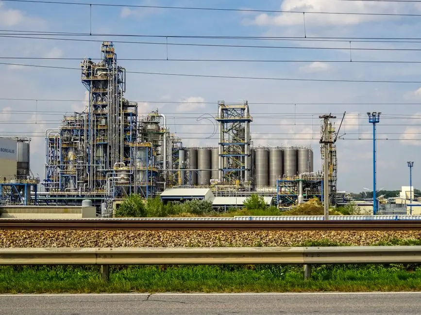
The reclaim-side block flow is where most legacy designs are under-built. At 28 nm, a single RO polish on blended rinse was often enough. At 18A, four sidestreams must be split, treated separately, and blended only at the make-up header—never upstream of an RO. The table below is the block flow to walk project leadership through in a 30-minute design review.
| Sidestream | Source | Key Contaminants / Loading | Treatment Block | Reclaim Quality Before Blend |
|---|---|---|---|---|
| General rinse reclaim | Quick-dump-rinse (QDR) overflow, cascade rinses | Low TDS, trace TOC | Carbon filter → RO → UV-polish | TOC < 5 ppb, resistivity > 10 MΩ·cm, blended at 20–30% of make-up |
| CMP sidestream | CMP tool effluent, post-CMP brush rinses | 50–500 mg/L TSS (silica, ceria slurries), trace metals | DAF → lamella clarifier → RO polish | TSS < 5 mg/L before RO; slurry particles must be removed upstream of any membrane |
| Copper reclaim | Cu plating rinse, Cu CMP post-rinse | Copper 5–50 mg/L, sulfate, organic additives | Chelating ion exchange OR electro-winning → RO polish | Cu < 0.05 mg/L; > 90% Cu recovery |
| Fluoride / BOE sidestream | Buffered oxide etch (BOE), NH₄F/HF baths | F⁻ 100–1,000 mg/L, NH₄⁺, suspended silica | Calcium precipitation (lime or CaCl₂) → solids separation → RO polish | F⁻ < 30 mg/L before blend |
CMP effluent is the most common membrane-fouling source in advanced-node reclaim loops. A typical CMP tool discharge carries 50–500 mg/L total suspended solids (TSS) of silica or ceria slurry, with particles clustered in the 0.1–10 µm range. Blending that stream into general reclaim ahead of RO will foul elements within hours. The accepted block starts with pH adjustment to 7–8. Dissolved air flotation then runs an air-to-solids (A/S) ratio of 0.03–0.08 (lower for silica, higher for ceria) to float bulk slurry. Lamella clarifiers follow at 20–40 m/h surface loading to capture residual fines. DAF underflow goes to solids handling. Clarifier overflow feeds an RO dedicated to the CMP loop, with permeate blending back to the make-up header.
Copper reclaim is non-negotiable at 18A. Damascene copper plating and copper CMP generate spent rinse with copper at 5–50 mg/L. Sending that stream straight to the general reclaim RO risks copper breakthrough into make-up, where it plate-outs on wafer surfaces and kills yield. The standard block is a chelating ion-exchange skid (iminodiacetic or aminomethylphosphonic acid functional groups) or an electro-winning cell designed for > 90% copper recovery. Treated effluent is then polished through RO before blending. MBR-integrated wastewater treatment trains are sometimes added downstream of the clarifier to capture organic plating additives that RO rejects but that build up in the concentrate loop.
The fluoride sidestream handles BOE, NH₄F, and dilute HF wastes carrying 100–1,000 mg/L fluoride. Calcium precipitation with lime (Ca(OH)₂) or CaCl₂ at pH 8–9 drives Ca²⁺ + 2F⁻ → CaF₂(s), with stoichiometric Ca dose plus 5–10% excess. Sludge production is significant—typically 1.5–2.0 kg dry CaF₂ per m³ of treated wastewater at the upper fluoride range. Clarifier underflow must be dewatered separately from CMP sludge. Clarified effluent, with fluoride reduced to < 30 mg/L, goes to RO for final polish before blending.
Reclaim Rate Trade-Off: Water Savings vs. Capex Complexity
Reclaim rate is the metric steering committees watch first, and it is often oversold in early concept reviews. Each 5% step in reclaim rate typically requires one additional treatment loop. That step also adds roughly 8–15% to total water-treatment CapEx per m³/day of installed capacity (HydropureWater field data, 2026, for fab-class water trains).
The mature-node baseline is 70–85% reclaim with a single RO polish on blended rinse—no sidestream treatment, no copper loop, and no fluoride precipitation. The advanced-node target is 85–95% reclaim. That gap is exactly the cost of the three sidestreams above. Hitting 90% reclaim without copper recovery is not a defensible design at 18A. Copper breakthrough risk forces the loop whether or not reclaim percentage alone justifies it. Sound Intel UPW reclaim design therefore prices the copper block as mandatory, not optional.
Local water cost and discharge limits set the upper end. Arizona, Ohio, and Israel fab sites face acute water-stress permitting. Policy Matters Ohio (March 2026) notes Intel has spent nearly $179 million on the Ohio One water reclamation plant. About $123 million in ARPA reimbursements had already been drawn against a $300 million state grant package. Advanced fabs can draw roughly 10 million gallons of UPW per day. They often need 1,400–1,600 gallons of municipal water to make 1,000 gallons of UPW. The same brief cites TSMC’s Arizona reclaim plant targeting 90%+ recycling (near zero liquid discharge). Earlier project talk treated 90%+ reclaim as a voluntary stretch. Water-stressed sites now treat it as a practical permit and community condition for greenfield capacity.
Pushing reclaim from 90% to 95% usually means adding a second-pass RO on general reclaim permeate. It also means tightening fluoride precipitation to recover more blowdown, which moves CapEx into the 12–15% step. The decision rule used on recent advanced-node projects is simple. If local industrial water cost exceeds roughly $4–6/m³ and discharge limits are tightening, the 95% train pays back in 4–7 years on water savings alone, before counting avoided intake expansion. Below $3/m³, the 85% train is usually the economic optimum, even at advanced nodes.
Who This Is For and Next Step
This guide is for process, facilities, and EPC teams sizing UPW and reclaim trains for 18A/14A-class expansions. It also serves procurement managers comparing sidestream CapEx against permit risk. Teams running mature-node fabs with stable copper and CMP loads, and with local water below about $3/m³, can usually stay on a simpler 70–85% reclaim polish without the full copper/fluoride split. If your basis-of-design needs a sidestream block flow, recovery target, or polish skid comparison for an advanced-node expansion, request a fab water system quote with your design flow and chemistry envelope.
Frequently Asked Questions
What UPW resistivity and TOC targets must an advanced-node fab hold in 2026?
Advanced-node UPW loops still target 18.2 MΩ·cm resistivity at 25 °C, but must hold that value continuously under tool-load swings. TOC must stay below 1 ppb, typically 0.5–0.8 ppb in practice, with dissolved silica under 1 ppb. Those limits force UV TOC destruction, higher mixed-bed polish capacity, and tighter particle control than a 28 nm loop designed for 3–5 ppb TOC.
Why can’t a 28 nm reclaim train handle 18A copper and CMP waste?
Copper plating and copper CMP rinses carry 5–50 mg/L copper, while CMP slurry streams carry 50–500 mg/L TSS. A single blended RO sees copper breakthrough and rapid membrane fouling within hours if slurry is not removed first. Advanced-node designs split copper, CMP, fluoride, and general rinse into separate blocks and blend only after polish at the make-up header.
What reclaim rate should an Arizona or Ohio advanced fab target?
Most advanced-node projects target 85–95% reclaim. Water-stressed sites increasingly treat 90%+ as a practical permit and community condition rather than a voluntary stretch. If industrial water exceeds about $4–6/m³, a 95% train with second-pass RO often pays back in 4–7 years; below $3/m³, an 85% train is usually the economic optimum even at 18A.
How has the Intel Ohio One water reclaim schedule changed?
Earlier briefings placed Ohio One tool-in near late 2026–2027. Intel’s Q2 2025 guidance, as summarized in March 2026 reporting, moved the first Ohio module to 2030–2031. The dedicated water reclamation plant remains critical: Intel had spent nearly $179 million on it by early 2026, with about $123 million reimbursed under Ohio’s ARPA grant package.
Which equipment blocks are mandatory before reclaim RO at advanced nodes?
CMP streams need DAF plus lamella clarification to reach TSS below 5 mg/L before any RO. Copper streams need chelating ion exchange or electro-winning to below 0.05 mg/L Cu with greater than 90% copper recovery. Fluoride/BOE streams need calcium precipitation to below 30 mg/L F⁻ before blend. Skipping any of those blocks is the usual root cause of early membrane failure or yield loss.