A SiC membrane wastewater treatment system removes 95%+ COD and 92-97% TSS at 150-300 LMH flux (3x polymeric rates), tolerates pH 0-14 and 80°C feeds, and cuts OPEX roughly 30% versus polymeric membranes. Installed CAPEX spans $2M-$20M by scale.
Why Choose a SiC Membrane Wastewater Treatment System Over Polymeric or Ceramic?
SiC membrane wastewater treatment systems deliver 150-300 LMH flux at 0.5-3 bar TMP, survive pH 0-14 and 80°C, and carry 10-15 year membrane lives. Polymeric systems cost $150-$300 per m² but foul 20-40% monthly and need replacement every 3-5 years, so lifecycle math favors SiC in harsh streams.
Silicon carbide membranes owe their durability to a covalent bond structure that resists the swelling, hydrolysis, and embrittlement attacking the ionic bonds of alumina ceramics and the long-chain hydrocarbons of PVDF or PES polymers. That molecular stability holds across the full pH 0-14 window, where polymeric membranes typically swell or degrade outside the pH 2-11 range. Surface chemistry leaves SiC naturally hydrophilic, so organic oils and proteins repel rather than anchor, sustaining flux rates of 150-300 LMH in semiconductor, pharmaceutical, and chemical wastewater service (HydropureWater field data, 2025). Strong oxidants such as chlorine and ozone that dissolve polymer matrices barely mark the SiC surface.
Thermal behavior separates the materials further wherever hot process streams reach the membrane. SiC modules keep filtering reliably at feed temperatures up to 80°C, while standard PVDF or PES membranes lose structural tension and filtration efficiency above 40°C. Alumina ceramics take more heat but remain susceptible to thermal shock during backwash cycles, where SiC's thermal conductivity dissipates heat rapidly and prevents the micro-cracking common in brittle alumina alternatives.
| Material Property | SiC (Silicon Carbide) | Polymeric (PVDF/PES) | Ceramic (Alumina) |
|---|---|---|---|
| Standard Flux Rate (LMH) | 150 - 300 | 50 - 100 | 80 - 120 |
| Chemical Resistance (pH) | 0 - 14 | 2 - 11 | 1 - 13 |
| Max Temperature (°C) | 80 (Standard Module) | 40 | 100+ (Fragile) |
| Oxidant Tolerance | High (Ozone, Cl2) | Low (Degrades) | Moderate |
| Hydrophilicity (Contact Angle) | < 30° | 60° - 90° | 40° - 50° |
SiC Flat Sheet Membrane MBR Specifications for 2027 Systems
SiC flat sheet membranes for submerged MBR duty carry a 0.1-0.5 μm pore rating, run at 0.5-3.0 bar TMP, and stretch backwash intervals to once per 24 hours. The 2027 engineering focus for these trains is submicron precision paired with lower-energy hydraulics. Modern SiC flat sheet membrane modules for submerged MBR applications target colloidal silica, metal hydroxides, and pharmaceutical active ingredients (APIs) with that 0.1 to 0.5 μm cut-off. Operating at lower transmembrane pressure than polymeric systems—typically 0.5 to 3 bar—trims the specific energy consumption (SEC) of the feed pumps.
Module architecture has consolidated into two families: the flat sheet (DF Series) for submerged MBR applications and tubular designs for high-solids sidestream processes. Backwash demand is where the material chemistry pays out daily: polymeric systems require cleaning every 4-6 hours, while SiC systems often operate 24 hours between backwash cycles thanks to superior fouling resistance. An integrated cross-flow aeration mechanism blows coarse bubbles across the membrane surface, preventing a cake layer from forming at all. Most plants we size for food and pharmaceutical feeds hold aeration near the bottom of the 0.5-1.0 Nm³/m²/h band and still hit flux targets.
| Parameter | Engineering Specification (2027 Standard) |
|---|---|
| Pore Size Distribution | 0.1 μm (Ultrafiltration) to 0.5 μm (Microfiltration) |
| Operating Pressure (TMP) | 0.5 – 3.0 bar |
| Backwash Frequency | 1x per 24 hours (Application dependent) |
| Cleaning-in-Place (CIP) Interval | 30 – 90 days |
| Membrane Thickness | 2.0 – 5.0 mm (Flat Sheet) |
| Aeration Scouring Rate | 0.5 – 1.0 Nm³/m²/h |
SiC vs Polymeric vs Ceramic: Head-to-Head Performance and Cost Comparison
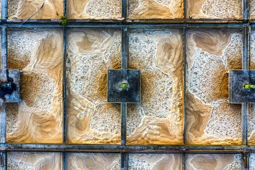
In side-by-side evaluations on semiconductor wastewater containing hydrofluoric acid and abrasive polishing slurries, SiC membranes demonstrated a 10-year design life against 2-3 years for PVDF membranes that suffered chemical embrittlement. The head-to-head question for procurement is whether higher initial material cost buys back its premium in avoided OPEX, and the crossover usually lands within two polymeric replacement cycles. SiC's tolerance for high-strength oxidants also permits aggressive cleaning protocols that would dissolve a polymeric matrix within minutes.
Fouling metrics tilt the same way in pharmaceutical service, where protein fouling typically reduces polymeric flux by 60% within the first month of operation. SiC maintains 90% of its clean water flux (CWF) on the same duty because its surface roughness sits at Ra < 0.1 μm, far smoother than the 0.5-1.0 μm Ra of PVDF. Ceramic alumina membranes offer a middle ground, but their lower flux rates require a 40% larger footprint for equal permeate volume, increasing civil engineering costs. Where silica recovery matters more than flux, a ceramic membrane water recovery route built on ultrafiltration suits dicing and grinding streams better.
| Parameter | SiC (Silicon Carbide) | Polymeric | Ceramic (Alumina) | Winner |
|---|---|---|---|---|
| Flux Rate (LMH) | 150 - 300 | 50 - 100 | 80 - 120 | SiC |
| Lifespan (Years) | 10 - 15 | 3 - 5 | 8 - 12 | SiC |
| Fouling Rate (%) | < 5% per month | 20 - 40% per month | 10 - 15% per month | SiC |
| CAPEX ($/m²) | $800 - $1,500 | $150 - $300 | $600 - $1,000 | Polymeric |
| OPEX ($/m³) | $0.15 - $0.30 | $0.45 - $0.70 | $0.25 - $0.40 | SiC |
Zero Liquid Discharge SiC Membrane Cost: $2M–$20M CAPEX by Scale and Application
Zero liquid discharge SiC membrane cost runs from roughly $2M for a 50 m³/h chemical-plant train to beyond $20M for a 500 m³/h semiconductor fab facility. Required membrane surface area drives the bill first, followed by the complexity of integrated pre-treatment and post-treatment stages. A base-level system for a chemical plant processing 50 m³/h—primary clarifier, MBR tank with SiC modules, basic automation—typically starts at $2M. A full-scale 500 m³/h ZLD facility for a semiconductor fab, built around RO systems for ZLD applications paired with SiC membranes plus evaporators, can exceed $20M.
Against that CAPEX sits a 30% OPEX reduction versus polymeric systems, realized through three channels: 50% less energy for backwash pumping, near-elimination of CIP chemical spend, and avoidance of frequent membrane replacement. For a facility facing EPA non-compliance fines that can reach $500,000 per year, that reliability compresses payback to 3 to 5 years. The full detailed OPEX savings analysis for SiC vs polymeric membranes breaks down each channel, and fab-scale cost benchmarks appear in Chip Fab Wastewater Treatment: 2026 Engineering Specs, Zero-Fouling Design.
| System Scale | Application Type | Estimated CAPEX | Key Cost Drivers |
|---|---|---|---|
| 50 m³/h | Pharma Pre-treatment | $2M - $4M | Membrane area, CIP skid |
| 150 m³/h | Chemical MBR | $6M - $9M | Automation, Aeration systems |
| 500 m³/h | Semiconductor ZLD | $15M - $20M+ | RO integration, Evaporators |
Zero-Fouling Design: How SiC Handles High-Solids Wastewater Directly
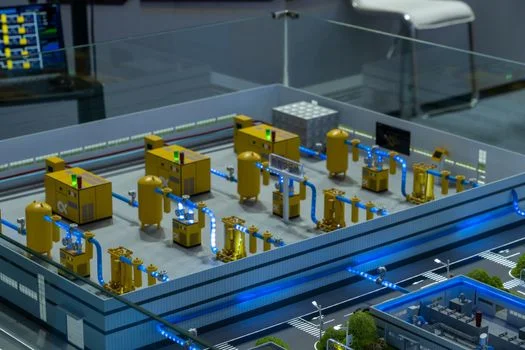
Zero-fouling, as the term applies to SiC equipment, means processing high-solids influent without the catastrophic flux decline that organic membranes suffer. Surface roughness below Ra 0.1 μm—against 0.5-1.0 μm Ra in PVDF—leaves bacterial biofilms and inorganic scale little anchorage. Cross-flow velocities of 3-5 m/s then sweep away whatever deposits before it consolidates into a cake.
A semiconductor wastewater treatment case study with SiC membranes demonstrated the effect on a plant handling 300 mg/L of influent TSS. The previous polymeric system required 24 hours of downtime per week for manual cleaning and recovery; the SiC installation reduced unplanned downtime to less than 1 hour per year. Engineers must still hold aeration at 0.5-1.0 Nm³/m²/h, which creates localized turbulence preventing concentration polarization at the membrane interface. And because SiC remains a ceramic, modules should sit in shock-absorbing stainless steel frames wherever vibration from heavy industrial environments like mining reaches the tank.
Selecting the Right SiC System: A Five-Step Decision Framework
Selection is a stream-characterization exercise first and a membrane decision second. Engineers should follow a five-step framework to ensure the technology matches the application requirements:
- Characterize the stream: pH swing, temperature range, TSS, oil and grease, oxidant residual, and the target contaminants (COD, APIs, colloidal silica).
- Pilot at design flux on real feed for 2-4 weeks, including at least one fouling-and-recovery cycle, to confirm that 150-300 LMH holds beyond clean-water tests.
- Fix the hydraulics before quoting: TMP of 0.5-3 bar, aeration scouring of 0.5-1.0 Nm³/m²/h, and backwash cadence sized to once per 24 hours.
- Cost the lifecycle, not the skid: SiC CAPEX of $800-$1,500 per m² against a 10-15 year life, OPEX of $0.15-$0.30 per m³, and CIP intervals of 30-90 days.
- Plan integration early—CIP skid, automation scope, shock-mounted module frames, and the ZLD interfaces (RO, evaporators) your recovery target demands.
Land-constrained sites change the layout before the membrane does. An Underground Package Sewage Treatment Plant (WSZ Series) buries the biological and settling stages below grade, freeing surface area for membrane tanks and future expansion. For municipal-strength feeds—BOD-dominated, near-neutral pH, moderate TSS—polymeric MBRs often win on price; SiC earns its premium only when chemistry, temperature, or downtime risk turns severe.
Next Steps: Pilot Data, Budget Envelope, and Quotation
Bring three numbers to any vendor conversation: design flow in m³/h (US gpd), a complete wastewater analysis, and the recovery or discharge target. Those inputs size membrane area, place the project inside the $2M-$20M CAPEX brackets above, and decide whether ZLD unit operations join the scope. Flag your schedule as well, because SiC module lead times run longer than polymeric with fewer sintering lines serving the market. For a budgetary quotation on a SiC train sized to your stream, send the inquiry form with your water analysis attached.
Frequently Asked Questions
Why choose a SiC membrane for semiconductor wastewater?
SiC membranes survive hydrofluoric acid, abrasive polishing slurries, and oxidizing cleans that embrittle PVDF within 2-3 years, and they carry a 10-year design life on fab streams. Their hydrophilic surface repels CMP slurry organics, holding 90% of clean water flux where polymeric modules lose 60% in a month. As ZLD pretreatment, SiC also shields downstream RO and evaporators from colloidal silica.
What should you know about SiC membrane CAPEX breakdown industrial scale?
Membrane area sets the baseline at $800-$1,500 per m² of SiC, but the installed total scales with scope. A 50 m³/h pharma pre-treatment system starts near $2M, a 150 m³/h chemical MBR runs $6M-$9M, and a 500 m³/h semiconductor ZLD facility reaches $15M-$20M or more. Automation, aeration systems, CIP skids, and RO or evaporator integration move the total as much as module count.
How often do SiC membranes need backwash and CIP?
SiC systems typically backwash once per 24 hours, against every 4-6 hours for polymeric trains, because the smooth hydrophilic surface resists cake formation. Cleaning-in-place intervals run 30-90 days depending on feed strength. Oxidant tolerance lets plants run aggressive CIP chemistry without shortening the 10-15 year membrane life.
Can SiC modules drop into an existing polymeric MBR tank?
Retrofitting usually works where tank hydraulics can deliver the required aeration scour and the modules sit in shock-mounted frames. SiC flat sheets run at 150-300 LMH, so a like-for-like swap often cuts required membrane area or frees capacity for higher load. Verify diffuser placement, bottom slopes, and lifting clearances first, because SiC cassettes weigh more than polymeric ones.