Separate the Wastewater Streams Before Choosing Equipment
A Himeji data center needs a treatment train matched to its cooling design, measured blowdown, chemistry, and intended discharge or reuse route. Open-loop evaporative systems generally require control and treatment for concentrated salts, treatment chemicals, suspended solids, metals, and heat. Closed-loop systems usually produce smaller periodic discharges, while direct liquid cooling requires coolant-specific assessment. Equipment capacity should not be specified from server load or facility area: first meter makeup and blowdown, record operating conditions, and confirm final selection and Japanese acceptance criteria with the responsible authority.
Start by drawing each liquid stream as a separate balance. Open-loop evaporative cooling removes water as vapour while retaining most non-volatile constituents. Its blowdown can therefore carry salts, corrosion inhibitors, biocides, suspended solids, metals, and elevated temperature. Closed-loop systems do not intentionally evaporate circulating water; leakage, maintenance, and system configuration produce smaller, periodic discharges. Once-through cooling requires a separate heat-load assessment because its discharge may differ substantially from tower blowdown.
Direct liquid or immersion cooling creates a different contamination boundary. Obtain the coolant safety data sheet, PFAS status, leak-control records, and treatment-acceptance criteria before combining this liquid with other wastewater. Conventional wastewater analysis cannot demonstrate whether a proprietary coolant is suitable for discharge or reuse.
Keep domestic sewage, equipment wash water, and coolant-bearing process water segregated until compatibility and sampling requirements are established. A practical stream map is:
| Stream | Characteristic condition | Information required before equipment selection | Initial segregation decision |
|---|---|---|---|
| Open-loop cooling-tower blowdown | Concentrated dissolved solids and treatment chemicals; possible suspended solids, metals, and heat | Makeup and blowdown flow, conductivity, cycles of concentration, temperature, pH, hardness, metals, biocides, and chemical programme | Keep separate until the outlet route and treatment objective are confirmed |
| Closed-loop cooling discharge | Generally smaller and periodic, arising from leaks, maintenance, and system design | Event frequency, discharge volume, fluid inventory, contamination history, and coolant or process-fluid identity | Segregate by event and fluid type |
| Once-through cooling discharge | Heat load and source-water chemistry dominate the assessment | Source-water analysis, temperature rise, withdrawal and discharge routes, flow profile, and applicable discharge conditions | Assess independently from tower blowdown |
| Direct liquid or immersion cooling discharge | Coolant-specific constituents may include constituents requiring specialized handling | Fluid SDS, PFAS status, leak controls, analytical methods, and acceptance criteria | Do not blend before compatibility review |
| Equipment wash water | May contain corrosion products, cleaning residues, oil, and suspended solids | Cleaning agents, rinse protocol, frequency, and segregated collection points | Collect separately pending sampling |
| Domestic sewage | Separate sanitary flow and treatment basis | Flow, occupancy basis, and applicable sewer or on-site treatment requirements | Exclude from industrial cooling-blowdown sizing |
The stream boundary must remain visible through design, sampling, and commissioning. For broader route context, the project team can evaluate discharge, partial reuse, and cooling reuse, but the Himeji decision still requires site-specific evidence.
Build a Measured Water Balance Before Sizing Treatment
Treatment demand must come from measured cooling-water flows, not server load or facility area. Install calibrated metering for makeup and blowdown, identify drift and unaccounted losses, and correlate the readings with basin conductivity, heat rejection, operating hours, and cycles of concentration. The final treatment design should use the commissioned site balance.
- Record makeup flow, blowdown flow, basin conductivity, heat rejection, and operating hours at a consistent interval.
- Reconcile the readings with evaporation, drift, leakage, overflow, and chemical consumption.
- Determine average and peak treatment flow, contaminant loading, reuse demand, and residual flow.
- Use those measured values as the basis for equipment guarantees and acceptance tests.
For preliminary planning, use blowdown ≈ evaporation ÷ (CoC − 1) − drift, where CoC is cycles of concentration. This relationship is not a substitute for a site-specific balance after commissioning. EPA’s Water Efficiency Management Guide: Mechanical Systems (2017), as reported by iTech Guides in the HydropureWater regional guide, gives an approximate evaporation rate of 1.8 gallons per ton-hour of cooling. The same source reports drift losses of 0.05%–0.2% of cooling-tower flow and states that modern drift eliminators can reduce drift below 0.005%. These values provide preliminary context only; site metering remains the sizing basis.
Check conductivity-controlled blowdown against the calculated balance. A lower measured discharge can conceal leakage, drift, overflow, or a faulty flow meter. Conversely, shortening the blowdown interval increases the frequency of residual handling and may alter chemical demand. Increasing CoC cannot be assumed to reduce discharge: makeup chemistry, scaling, corrosion, biological control, and treatment-chemical limits must permit the selected concentration.
| Measured or verified input | Engineering use | Acceptance record |
|---|---|---|
| Calibrated makeup and blowdown meters | Establishes withdrawal and hydraulic treatment demand | Meter calibration, installation record, and synchronized operating data |
| Evaporation, drift, leakage, and overflow | Completes the cooling-water balance and exposes uncontrolled losses | Reconciliation log against the preliminary mass-balance equation |
| Basin conductivity and CoC | Indicates dissolved-solids concentration and blowdown control performance | Trend data and control-loop calibration record |
| Heat rejection and operating hours | Links cooling demand to evaporation and peak discharge | Chiller and tower design data linked to metered operation |
| Representative chemistry | Determines contaminant loads and chemical requirements | Laboratory analysis with sampling dates and methods |
| Reuse target and residual destination | Defines recovered-water demand and residual treatment flow | Approved water balance and residual route |
Commercial Water Lab, cited in the regional guide, reports broad withdrawal benchmarks of up to 300,000 gallons per day for a medium-sized data center and up to 5 million gallons per day for a hyperscale facility, based on a University of Georgia Extension publication by Saha in 2026. These are contextual withdrawal figures, not Himeji treatment-sizing inputs. They cannot establish the flow that the proposed Himeji equipment must handle.
Match the Treatment Train to the Discharge or Reuse Route
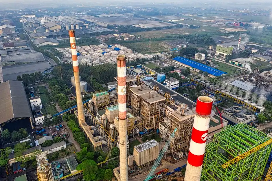
The outlet route determines the treatment objective, so it must be selected before comparing equipment. For sewer discharge, request the responsible Himeji authority’s current pretreatment guidance, permit path, sampling method, connection conditions, prohibited materials, and numerical acceptance limits. The supplied research contains no Himeji-specific numerical limits, so no concentration or flow criterion should be inserted into the project brief without confirmation from the authority or another competent Japanese authority.
For controlled receiving-water discharge, assess thermal effects as well as chemistry. Warm discharge can reduce dissolved oxygen and stress aquatic systems; a chemical treatment train alone does not resolve the thermal component. For cooling reuse, define the receiving cooling demand, feed-water chemistry, scaling and corrosion limits, biological-control requirements, and operating envelope. A generic potable-water target does not automatically provide the safest or most economical reuse specification.
| Treatment function | Use it when | Key limitation to verify | Residual or downstream issue |
|---|---|---|---|
| Equalization and chemical control | Flow, load, or pH varies enough to destabilize downstream treatment | Dose must be based on influent variability and the cooling programme; oversized tanks do not remove incompatible contaminants | Chemical delivery waste and dosing-system isolation |
| DAF | Suspended solids, colloids, or oil and grease are present and compatible with flotation | Representative testing must establish capture, chemical demand, and feed compatibility | Recovered sludge and DAF residuals |
| Multimedia filtration | Particulate control is needed before chemical-sensitive or membrane processes | Confirm hydraulic capacity and filtration performance with representative water | Spent media or backwash |
| UF | Bacteria, colloids, and suspended solids must be reduced, or UF is required as pretreatment for RO | Define recovery, cleaning, membrane loading, and downstream feed chemistry | Backwash, cleaning waste, and membrane replacement |
| MBR | The required outlet quality justifies biological treatment and the organic load is sufficiently biodegradable | Verify biodegradability, process control, footprint, maintenance, and membrane fouling | Sludge handling and disinfection |
| RO | Dissolved-salt removal is required for reuse or a stringent outlet specification | Confirm hardness, scaling, fouling, recovery, pretreatment, and concentrate destination | Concentrate and membrane replacement |
| Disinfection | The selected reuse or discharge route requires pathogen control | Specify the route-specific organism, analytical method, dose, and residual limit | Disinfection by-products and chemical residual |
Where solids and oil removal are required, a DAF system for blowdown solids and oil removal is relevant only after representative testing confirms compatibility and defines recovered-solids handling. For a UF+RO reuse route, an ultrafiltration system for cooling-water reuse pretreatment should be evaluated as part of the complete train, not as an isolated capacity claim.
Reuse carries a measurable energy trade-off. The 2026 life-cycle study Reclaiming Cooling: Wastewater Reuse as a Strategic Resource for Data Center Water Management by Open Engineering Inc. found that the wastewater case had about twice the global warming potential of the freshwater case, with treatment energy responsible for roughly 80% of the difference. Its UF+RO wastewater scenario used over five times the freshwater scenario’s energy. Higher CoC partly offset the burden by reducing blowdown and chemical consumption, but the result was site-specific. The Himeji comparison must therefore include energy, chemical demand, recovery, and residual handling rather than water savings alone.
Verify Performance, Residuals, and Japanese Acceptance
Performance claims must be established on representative Himeji feed conditions before chemical dosing, membrane loading, solids capture, or recovery rates are fixed. Conduct pilot or bench testing on the actual water and chemical programme. A guarantee should separately cover average treatment flow, peak treatment flow, eventual residual-disposal flow, treated-water quality, equipment availability, automatic controls, and chemical consumption. Nameplate capacity alone does not demonstrate treated-water performance.
Define sampling at makeup, tower basin, treatment inlet, each treatment stage, final discharge or reuse point, and concentrate or sludge removal. The baseline monitoring specification should include flow, conductivity, temperature, pH, suspended solids, turbidity, and hardness, plus the chemical parameters actually used at the facility. Add stage-specific differential pressure and flow measurements for filtration, UF, RO, or other pressure-driven equipment.
Configure separate alarms for makeup flow, blowdown flow, tank level, differential pressure, chemical dosing, high conductivity, and high turbidity. Each alarm needs a defined response: isolate a dosing pump, switch to a specified control setting, stop a process pump, or divert flow to equalization. An alarm that does not identify the affected stream and available response is incomplete.
Japan-specific acceptance requires a documented route and authority interface. The compliance record should identify the applicable sewer or receiving-water conditions, permit path, sampling instructions, numerical limits, connection requirements, analytical methods, and approved residual route. For zero-liquid-discharge objectives, identify the destination and treatment basis for concentrate, sludge, distillate, and spent media. These streams are part of the selected train, not residual issues to defer until after installation.
Pilot testing should also verify chemical consumption and the disposal or recovery pathway for every generated residual. Claims involving direct liquid cooling or PFAS require project-specific analytical methods, detection limits, and acceptance criteria; they cannot be inferred from conventional wastewater results. During commissioning, reconcile treated flow, recovered flow, and residual flow with the measured cooling balance so that treatment failure, leakage, and uncontrolled blowdown cannot be confused.
Complete the Himeji Treatment Selection Worksheet

The procurement decision becomes auditable when each missing input has an owner and an approval action. The worksheet should be completed before equipment capacity, treatment chemistry, recovery, or compliance limits are placed in a purchase specification.
| Responsible party | Data or decision to provide | Equipment check or approval task | Completion evidence |
|---|---|---|---|
| Owner or cooling contractor | Cooling design, operating hours, heat rejection, makeup and blowdown data, basin chemistry, chemical programme, and measured water balance | Confirm actual cooling configuration and operating envelope | Approved design basis, meter data, water balance, and chemical inventory |
| Wastewater engineer | Stream segregation, contaminant loads, preliminary process train, average and peak treatment flow, sampling plan, and residual balance | Select the shortest train that meets the confirmed outlet route | Signed process basis, water and contaminant balance, and P&ID |
| Equipment supplier | Guaranteed flow envelope, feed limits, automation, controls, backwash or cleaning, chemical consumption, and performance-test conditions | Demonstrate fit for representative feed and complete the control narrative | Technical offer, guarantee schedule, pilot results, and control drawings |
| Himeji authority or qualified Japanese compliance adviser | Discharge route, applicable permit or sewer conditions, sampling requirements, numerical acceptance criteria, and residual route | Confirm approval path and required evidence | Written confirmation, permit conditions, or documented authority correspondence |
| Project approver | Reviewed worksheet, pilot report, guarantees, and authority responses | Release the treatment-train specification and procurement package | Signed design freeze and procurement release |
Do not close an item with “TBC” where it affects equipment selection. Record the missing information, its owner, and the date required. This keeps the Himeji data-center wastewater decision linked to actual cooling operations rather than a generic treatment catalogue.
Frequently Asked Questions
Why can’t facility area or server load determine treatment capacity?
Facility area and server load do not establish cooling-water flow, blowdown volume, contaminant concentration, or peak discharge. The equipment basis must come from the measured cooling water balance, operating profile, feed chemistry, and selected outlet route.
When should a Himeji project use DAF, UF, MBR, RO, or chemical dosing?
Use DF for compatible solids, colloids, or oil; UF for bacteria, colloids, suspended solids, or RO pretreatment; MBR where biodegradability and outlet quality justify biological treatment; RO where dissolved-salt removal is required; and chemical dosing where verified chemistry shows it is required. Pilot testing must confirm each function.
What must be obtained before selecting Japanese treatment equipment?
Obtain the confirmed Himeji discharge or reuse route, authority requirements, sampling methods, numerical acceptance criteria, permit conditions, feed analyses, measured flows, and residual destination. The supplied research contains no Himeji-specific numerical limits, so request them rather than inserting assumed values.
How should the project compare cooling-water reuse with treatment energy and residuals?
Compare recovered water against treatment energy, chemical demand, recovery, concentrate volume, sludge or spent-media disposal, and the approved disposal route. Open Engineering Inc.’s 2026 study found that wastewater reuse carried a higher energy burden in its UF+RO scenario, so water savings alone do not establish the preferred route.