What Wastewater Streams Does a Kagoshima Data Center Need to Treat?
A Kagoshima data center usually needs a treatment train based on its cooling design, not a universal treatment package. Open-loop evaporative systems need blowdown control because evaporation concentrates salts and treatment chemicals; closed-loop systems generally produce smaller, periodic discharges, while direct liquid cooling can introduce coolant-specific contaminants. The required train may combine equalization, solids removal, filtration, pH and chemical control, disinfection, and reuse or final disposal. Selection requires measured makeup and blowdown flow, conductivity, temperature, pH, suspended solids, hardness, metals, biocides, and the intended sewer, receiving-water or zero-liquid-discharge route. Japanese permits and sewer-acceptance limits must be confirmed for the site.
Open-loop evaporative cooling removes water as vapour while retaining most non-volatile constituents in the circulating water. Commercial Water Lab lists salts, minerals, biocides, corrosion inhibitors and heavy metals among constituents that may occur in cooling-tower blowdown. That stream should therefore be assessed according to its actual water chemistry, not by assuming that it is equivalent to domestic sewage.
Closed-loop systems do not intentionally evaporate the circulating water, so their discharge is generally smaller and periodic; the amount returned depends on leaks, maintenance and the system design. Direct liquid or immersion cooling creates a different boundary because the discharged liquid may contain product-specific coolant constituents, including refrigerants or PFAS compounds. Commercial Water Lab states that these fluids may require specialized handling.
Domestic sewage, equipment wash water and coolant-bearing process water should remain separate streams until compatibility, sampling and treatment requirements have been established. Equipment wash water can contain corrosion products, cleaning residues, oil and suspended solids. Combining it with cooling blowdown may increase treatment complexity or invalidate an acceptance basis.
Withdrawal, consumption and discharge are separate quantities. KETOS reports that evaporative systems typically evaporate approximately 70–80% of withdrawn cooling water and return 20–30% as liquid wastewater. The remainder of the balance includes blowdown, drift, leaks and overflows.
The applicable Kagoshima sewer authority, receiving-water route, zoning conditions and permit path must be verified directly. United States NPDES and pretreatment frameworks described by Commercial Water Lab are international context, not Japanese acceptance criteria.
| Stream | Primary design issue | Information required before treatment selection |
|---|---|---|
| Open-loop cooling-tower blowdown | Concentrated salts, treatment chemicals, suspended solids and heat | Makeup, blowdown, conductivity, pH, temperature, hardness, metals, biocides and cycles of concentration |
| Closed-loop purge | Periodic volume and chemical composition that depend on the loop chemistry | Purge frequency, volume, coolant inventory and contamination history |
| Once-through cooling discharge | Thermal load and added treatment chemicals | Source-water quality, temperature rise, withdrawal and discharge routes |
| Domestic wastewater | Organic load, nutrients and pathogen control | Peak flow, occupancy basis and applicable sewer requirements |
| Equipment wash water | Suspended solids, oil, cleaning chemicals and metals | Cleaning agents, rinse protocol, frequency and segregated collection points |
| Direct-liquid-cooling discharge | Coolant-specific constituents and product compatibility | Fluid SDS, PFAS status, leak controls and treatment acceptance criteria |
For broader stream-definition guidance, see the regional data-center cooling blowdown treatment guide. The data-center blowdown sizing methodology provides a separate framework for converting operating data into treatment demand.
Quantify Cooling Water, Blowdown and Contaminant Loads
A defensible treatment flow cannot be selected from server load or the data-center site area; it begins with a measured cooling-water balance. Install metering for makeup and blowdown, record drift and unaccounted losses, and correlate flow with basin conductivity, heat rejection and operating cycles of concentration.
The controlling relationship is:
Makeup = evaporation + blowdown + drift + leaks and overflows.
For preliminary planning, the relationship commonly used is blowdown ≈ evaporation ÷ (CoC − 1) − drift, where CoC is cycles of concentration. It is not a substitute for a site-specific balance after commissioning measurements. Conductivity-controlled blowdown should be checked against the calculated balance so that a lower measured blowdown is not simply masking leakage, drift or an unreported discharge.
EPA’s Water Efficiency Management Guide: Mechanical Systems (2017), as reported by iTech Guides, gives an approximate evaporation rate of 1.8 gallons per ton-hour of cooling. The same source reports drift losses of 0.05%–0.2% of cooling-tower flow, while modern drift eliminators can reduce drift below 0.005%. These figures provide preliminary engineering context; site metering remains the basis for equipment sizing.
Commercial Water Lab cites broad consumption benchmarks of up to 300,000 gallons per day for a medium-sized data center and up to 5 million gallons per day for a hyperscale facility, based on the University of Georgia Extension publication by Saha in 2026. These are contextual benchmarks, not Kagoshima sizing inputs, and they describe withdrawal rather than the required treatment flow.
The operating concentration ratio changes the discharge burden. iTech Guides reports that increasing cycles of concentration from three to six reduces makeup water by 20% and blowdown by 50%. The reduction cannot be assumed to be available: makeup-water chemistry, corrosion risk, biological control, scaling and treatment-chemical limits must permit the higher concentration.
Use a sequential sizing procedure:
- Measure average and peak makeup flow under normal and maximum heat-rejection conditions.
- Determine evaporation, blowdown, drift, leaks and overflows from the measured water balance.
- Calculate dissolved-solids loading from conductivity, with hardness, chlorides and metals added where project data requires them.
- Apply the planned reuse fraction and calculate the residual final-discharge flow.
- Size equalization and treatment stages for peak hydraulic demand while confirming the residual disposal route.
Do not specify treatment capacity in m³/h until average and peak makeup, blowdown, recovery and reuse targets are known. Contaminant loads should be calculated from measured concentration and flow rather than inferred from a generic “salty wastewater” description.
| Input | Why it changes the design | Acceptable preliminary source |
|---|---|---|
| Makeup flow and water analysis | Sets withdrawal, chemical dosing, scaling risk and attainable cycles of concentration | Site meters and representative laboratory analysis |
| Blowdown flow and conductivity | Defines the primary hydraulic and dissolved-solids loading | Calibrated flow meter and online or laboratory conductivity |
| Heat rejection and operating hours | Connects cooling demand to evaporation and peak discharge | Chiller and tower design data, metered operation |
| Drift, leaks and overflows | Completes the water balance and exposes uncontrolled losses | Site measurements and operating records |
| Reuse and disposal targets | Determines treatment duty, recovered volume and residual flow | Approved project design basis |
Confirm the Japanese Discharge and Reuse Route
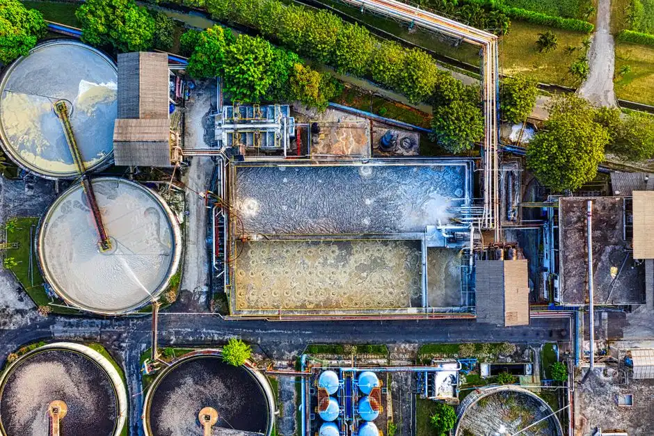
The discharge route determines the treatment objective, and it must be established before equipment selection. A sewer connection, on-site reuse, controlled receiving-water discharge and a zero-liquid-discharge objective impose different evidence requirements and residual-management duties.
For municipal sewer discharge, request the responsible Kagoshima sewer authority’s current pretreatment guidance, discharge permit, sampling method, connection conditions, prohibited materials and numerical acceptance limits. The supplied research contains no Kagoshima-specific numerical limits, so no concentration or flow criterion should be inserted into the project brief without confirmation from the authority or another competent Japanese authority.
For a controlled discharge to a receiving water, assess thermal effects as well as chemistry. Commercial Water Lab explains that warm discharge can reduce dissolved oxygen, stress aquatic organisms, promote algal blooms and contribute to long-term ecosystem changes. A chemical treatment train alone does not resolve the thermal component of that route.
For reuse, define the receiving demand. Reclaimed water intended for cooling makeup must satisfy the chemistry and operational limits of the cooling system; toilet flushing and process reuse have different requirements. A generic potable-water target does not automatically represent the safest or most economical specification.
Cooling-water reuse may reduce freshwater demand, but it also changes feed composition, chemical demand and treatment requirements. The project should therefore compare water conservation with the energy and chemical burden of advanced treatment before committing to a reuse-water membrane treatment train.
Direct liquid cooling requires product-specific information: coolant chemistry, safety data sheets, PFAS status, leak-control procedures and the treatment route accepted by the relevant authority. Conventional wastewater analytical results cannot establish that a coolant stream is suitable for discharge or reuse.
Commercial Water Lab distinguishes direct surface-water permits from municipal pretreatment requirements in the United States. Those mechanisms provide useful regulatory context but do not determine Japanese compliance. The Kagoshima authority must confirm the applicable Japanese approval path.
Facility-level public data may also be incomplete. Commercial Water Lab notes that confidentiality commitments often prevent publication of facility-level water-use and discharge information. Primary site measurements and direct regulator confirmation are therefore more reliable than industry-wide datasets for this decision.
The regional data-center cooling blowdown treatment guide provides wider discharge-route context, while the El Paso data-center treatment comparison illustrates why route-specific criteria must precede technology selection.
Choose a Treatment Train by Contaminant and End Use
The appropriate treatment train is the shortest sequence that meets the selected discharge or reuse specification while controlling solids, chemicals, concentrate and energy use. Pretreatment should remove material that would impair downstream biological or membrane processes; final treatment should meet the route-specific outlet requirement.
Equalization stabilizes flow and load before chemical dosing or solids removal. Chemical control manages pH and selected treatment chemicals, but its dose must be based on influent variability and the cooling programme. DAF can provide high-efficiency removal of suspended solids, colloids and oil or grease where flotation is compatible with the contaminants. For DAF pretreatment for data-center wastewater, representative testing should establish capture performance, chemical demand and recovered-solids handling.
Multimedia filtration and ultrafiltration provide different duties. Multimedia filtration can remove suspended material and provide particulate control. Ultrafiltration removes bacteria, colloids and suspended solids and can serve as pretreatment for reverse osmosis. For ultrafiltration pretreatment for cooling-water reuse, the design should define recovery, cleaning, membrane loading and downstream feed chemistry.
Biologically based treatment is appropriate where the relevant organic load is sufficiently biodegradable and the process can be controlled within the required footprint and operating envelope. The MBR versus conventional wastewater treatment comparison discusses the selection issues for projects with demanding effluent requirements. An MBR should not be selected merely because the application is called industrial wastewater; its value depends on the required outlet quality, bulk-liquid characteristics, membrane maintenance and residual handling.
Industrial reverse osmosis can polish dissolved salts and support reuse, but it requires appropriate pretreatment and introduces concentrate management and energy demands. For reuse or stringent discharge objectives, an MBR or RO-based train must be evaluated against organic biodegradability, hardness, scaling risk, recovery, concentrate destination and energy use.
The 2026 life-cycle study “Reclaiming Cooling: Wastewater Reuse as a Strategic Resource for Data Center Water Management,” published by Open Engineering Inc., found that the wastewater case had about twice the global warming potential of the freshwater case. Treatment energy accounted for roughly 80% of that difference. In its UF+RO wastewater scenario, wastewater energy use exceeded five times that of the freshwater scenario. Higher cycles of concentration partly offset the burden by reducing blowdown and chemical consumption, but the result is site-specific.
| Treatment option | Primary contaminant duty | Key failure condition to verify | Residual or downstream requirement |
|---|---|---|---|
| Equalization and chemical control | Flow, pH and chemical loading | Oversized tanks do not correct incompatible contaminants | Chemical delivery, sludge or dosing waste |
| DAF | Suspended solids, colloids, oil or grease | Contaminant properties unsuitable for flotation | Recovered sludge and DAF residuals |
| Ultrafiltration | Bacteria, colloids and suspended solids | Excessive fouling or unsuitable feed chemistry | Backwash, cleaning and membrane replacement |
| MBR or biological treatment | Biodegradable organics and suspended solids | Non-biodegradable load, toxicity or process instability | Sludge handling and disinfection |
| Reverse osmosis | Dissolved salts and polishing | Hardness, scaling, fouling and inadequate pretreatment | Concentrate disposal |
| Zero-liquid-discharge system | Broad removal with product recovery | Unverified feed composition and recovery assumptions | Salt, sludge, distillate and chemical residuals |
Sludge, membrane concentrate and spent media are part of the selected train, not residuals left until after installation. Before fixing chemical dosing, membrane loading, solids capture or recovery claims, conduct a site-specific pilot or bench test using representative water.
Build Monitoring, Automation and Performance Acceptance
Monitoring should verify both compliance and the water balance because treatment failure, leakage and uncontrolled cooling blowdown can otherwise look alike. The project brief should specify flow, conductivity, temperature, pH, suspended solids, turbidity, hardness and the chemical parameters actually used at the facility.
Use conductivity-controlled blowdown to minimize discharge only after the control loop is calibrated against makeup and basin conductivity. Confirm the result using the measured mass balance and chemical consumption. A conductivity setpoint alone cannot detect leaks, drift, overflows or a faulty flow meter.
Configure separate alarms for makeup flow, blowdown flow, tank levels, differential pressure, chemical dosing and high-conductivity or high-turbidity excursions. An alarm should identify the affected stream and the available response: isolate a dosing pump, switch to a defined control setting, stop a pump or divert the flow to equalization.
Sampling points should be specified at makeup, tower basin, treatment inlet, each treatment stage, reuse or final discharge, and concentrate or sludge removal. This arrangement supports mass-balance accounting and identifies whether a change originated in the cooling loop, pretreatment, final treatment or residuals handling.
| Monitoring point | Required evidence | Acceptance-test purpose |
|---|---|---|
| Makeup and tower basin | Flow, conductivity, temperature and pH | Verify water balance and cycles of concentration |
| Blowdown and treatment inlet | Flow and relevant contaminant analyses | Establish actual treatment loading |
| Each treatment stage | Stage-specific flow, pressure and water-quality results | Confirm removal across the complete train |
| Reuse or final discharge | Flow and route-specific quality parameters | Demonstrate the outlet requirement |
| Concentrate and sludge removal | Volume, frequency and destination records | Verify that residuals remain within their approved route |
Acceptance tests should cover guaranteed treatment flow, treated-water quality, equipment availability, automatic controls and chemical consumption. Nameplate capacity is not evidence of treated-water performance. The guarantee should distinguish average treatment flow, peak treatment flow and eventual residual-disposal flow.
Claims involving direct liquid cooling or PFAS require project-specific analytical methods, detection limits and acceptance criteria. They cannot be inferred from conventional wastewater results. Pilot testing should also verify chemical consumption and the disposal or recovery pathway for every generated residual.
The monitoring architecture in the regional data-center cooling blowdown treatment guide can be adapted to the Kagoshima route and permit basis.
Prepare the Information Buyers and Vendors Need
Comparable proposals begin with one common design basis, not a request for each vendor to choose its own interpretation of the project. The buyer should issue a one-page document containing the cooling type, daily and peak makeup, measured blowdown, heat rejection, water analysis, intended reuse fraction and discharge route.
Require every bidder to state its design flow, process diagram, equipment duty, recovery approach, concentrate destination, chemical consumption, control philosophy, acceptance criteria, footprint, utilities and commissioning plan. The bidder should also identify which values are measured, which are assumed and which require site testing.
Ask how the proposed train responds to upstream chemical changes, scaling, biofilm, variable conductivity and future capacity expansion. Also require a stated method for handling off-spec influent without creating an uncontrolled discharge.
Capacity comparisons must distinguish average flow from peak flow and treatment flow from eventual disposal flow. A bid based only on an equipment nameplate rate does not show whether the stated capacity addresses the actual Kagoshima design condition.
Delivery and commissioning commitments should be conditional on receipt of complete water analyses, confirmed site utilities, approved discharge route and representative testing. Treat a promised schedule made before those inputs are available as provisional.
Compare total installed cost and operating cost using the same design basis. The supplied research does not provide a defensible price for a Kagoshima installation, so a buyer should request quotations after receiving the flow, analysis, route, residual and site-utility inputs. The treatment-plant sizing and engineering specification guide can help structure that comparison.
Frequently Asked Questions
Why can’t a defensible m³/day treatment capacity be provided for a Kagoshima data center?
A defensible capacity requires measured or engineered site flows, including average and peak makeup, blowdown, drift, losses, recovery and reuse. Server load or facility area does not establish the cooling-water discharge rate. The buyer should first obtain meter data and a completed water balance, then ask vendors to size each treatment stage against the same peak and average conditions.
How should vendors be compared when each proposes a different data-center wastewater treatment capacity?
Compare bids against a common design basis rather than headline capacity. Each proposal should identify its design flow, process diagram, equipment duty, treated-water guarantee, chemical consumption, recovery method, residual destination, control philosophy and commissioning tests. Confirm that the proposed flow represents the stage duty—not merely equalization storage, feed pump capacity or eventual disposal volume. The regional data-center cooling blowdown treatment guide provides additional context for separating those capacities.
Which Japanese authority, permit and sewer documents should the buyer request?
Identify the Kagoshima sewer authority responsible for the proposed connection and request its current pretreatment guidance, discharge or connection permit, sampling method, prohibited-material rules and numerical acceptance limits. No Kagoshima-specific numerical limits were supplied in the research, so the buyer should not assume either Japanese or United States limits apply. Zoning, receiving-water and other approvals should also be confirmed for the selected route.
Can higher cycles of concentration reduce the treatment flow required in Kagoshima?
Yes, if the cooling-water chemistry and equipment materials permit it. iTech Guides reports that increasing cycles of concentration from three to six reduces makeup water by 20% and blowdown by 50%. The buyer should therefore request a water-balance calculation using measured conductivity and evaporation, while checking hardness, corrosion, scaling, biological control and chemical-use limits before accepting the reduction.
When are DAF, ultrafiltration, MBR and reverse osmosis appropriate?
DAF is a candidate for suspended solids, colloids and compatible oil or grease; ultrafiltration suits bacteria, colloids and suspended-solids removal and can pretreat RO; MBR is relevant where biological treatment and high-quality solids separation are justified; and RO can polish dissolved salts where pretreatment, scaling control, energy and concentrate disposal are acceptable. Representative testing should confirm contaminant behavior, fouling, chemical demand and recovery before the process is fixed.