Ion Exchange Process Flow Diagram at a Glance
An ion exchange system process flow diagram shows how wastewater moves through pretreatment, ion-exchange vessels and downstream reuse or discharge, while also showing the separate chemical and waste streams used during regeneration. During service, resin captures target ions and releases counter-ions; after breakthrough, the resin is regenerated with acid, brine or caustic and rinsed before returning to service. Parallel vessels allow treatment to continue while one vessel is being regenerated. For industrial wastewater, the diagram should also identify pretreatment, regeneration-waste handling, instrumentation and the intended product-water destination.
The complete process has two connected operating modes. The service path carries industrial wastewater or process water through optional pretreatment, feed pumping and flow control to one or more fixed-bed ion-exchange vessels. Treated water then passes through monitoring before reuse, further treatment or discharge. Ion exchange transfers unwanted ions onto the resin and releases counter-ions into the product stream; it does not destroy the captured contaminant.
The regeneration path is a separate hydraulic loop. A regenerant tank supplies acid, brine or caustic through a metering pump or eductor and valve manifold. The selected vessel is isolated from service, regenerated, rinsed and returned to duty. Concentrated regenerant and rinse discharge require a defined treatment, recovery or disposal route. For visual drafting conventions, see the industrial process flow diagram guide.
Conceptual flow: Feed → pretreatment → feed pump and flow control → ion-exchange vessel → product-water monitoring → reuse or discharge. Regeneration: regenerant tank → metering pump or eductor → valve manifold → ion-exchange vessel → collected regenerant and rinse waste.
This is a process-flow representation rather than a complete P&ID. A detailed P&ID adds individual valves, drains, vents, bypasses, alarms, interlocks and control loops. The first drawing should establish mass flow and operating intent; the P&ID should then show how that intent is controlled.
How the Treatment and Regeneration Cycles Work
Fixed-bed ion exchange continues exchanging ions while service flow passes through the resin bed, and contaminant breakthrough begins when the resin becomes sufficiently loaded with captured ions (PDH Academy, September 2023). The operating sequence should be shown as a closed loop rather than as a single treatment train.
- Service: Feed enters the vessel and moves through the resin bed. Cation exchange resin captures positively charged contaminants and releases counter-ions; anion exchange resin captures negatively charged contaminants and likewise releases counter-ions.
- Breakthrough: Loaded resin begins passing increasing amounts of the target contaminant. The treatment objective determines the monitoring parameter and the point at which a vessel must be taken out of service.
- Regeneration: A controlled chemical flow reverses the loading step and restores the resin to its initial ionic form. Cation regeneration commonly uses sulfuric or hydrochloric acid, while salt-based softening uses sodium chloride brine. Anion regeneration commonly uses a strongly basic solution such as sodium hydroxide (PDH Academy, September 2023).
- Backwash and rinse: Backwash, air scour and rinsing prepare the bed for service by removing residual regenerant and restoring an appropriate hydraulic condition. The sequence must be shown because rinse discharge may differ from the strongest regenerant stream.
- Return to service: After the defined rinse endpoint is met, the vessel is returned to the service path and monitored until required product-water quality is demonstrated.
Parallel ion exchange vessels are the practical arrangement when uninterrupted production is required. PDH Academy (September 2023) identifies parallel operation as a means of regenerating one vessel while the remaining vessels continue treatment. The valve manifold, not merely the vessel count, must make that operating sequence possible.
The treatment and regeneration circuits also need deliberate isolation. Service, regenerant and rinse flows must not create an unintended bypass between product water and waste streams. When reviewing an ion exchange valves, tanks, resin and monitoring components list, verify that each flow path corresponds to a defined operating step.
What Each Stream and Equipment Block Does

Each stream should have a defined source, destination, flow condition and monitoring point; otherwise the drawing does not support mass balance or control review. The equipment checklist below separates those functions.
| Stream or block | Engineering function | Review requirement |
|---|---|---|
| Industrial wastewater or process-water feed | Supplies the contaminants to be removed. | Identify the target contaminant, complete feed matrix, variability and intended recovery or reuse objective. |
| Pretreatment | Removes constituents that could foul resin or interfere with the intended separation. | Define project-specific limits for suspended solids, colloids, organics and other relevant constituents; the supplied research establishes no universal pretreatment limits. |
| Feed pump and flow control | Provides hydraulic delivery and service-flow control. | Show pump location, duty, control range, isolation and any required flushing path. |
| Ion-exchange vessel | Houses the resin and performs the ionic exchange. | PDH Academy (September 2023) identifies upper and lower manifolds, gravel underdrain, regenerant distributor and air-scour grid as typical components of a fixed-bed vessel. |
| Product-water monitoring | Confirms treatment performance and identifies breakthrough. | Monitor ions relevant to the application; the supplied research does not establish universal online sensor thresholds. |
| Regenerant tank, pump or eductor | Stores and meters the selected chemical. | Identify chemical form, concentration, containment, metering method and operator interface. |
| Valve manifold | Routes service, regeneration, backwash and rinse flows. | Show actuated and manual isolation, bypasses, drains, vents and the permitted valve states. |
| Rinse-water supply | Displaces residual regenerant and prepares the bed. | Define source, quality, control and destination of rinse discharge. |
| Regenerant and rinse waste | Carries captured contaminants out of the resin. | Define collection, segregation, neutralization, treatment, recovery and final disposal or reuse. |
Regeneration waste is not an incidental drain. Ion exchange concentrates captured ions into the regenerant discharge, and that stream requires its own process. The University of Cape Town study on continuous counter-current ion exchange documents an interlinked five-column pilot plant, regenerant-chemical recovery and concentration of dissolved feed components (University of Cape Town, 1979). This supports treating waste routing and chemical recovery as design elements rather than footnotes.
Emerging membrane research should be kept technically distinct from conventional resin regeneration. A 2026 American Chemical Society study examined lithium-ion recovery from battery wastewater using flow capacitive deionization and a ZIF-8-coated cation exchange membrane (American Chemical Society, 2026). That work shows current interest in membrane-based ion separation, but it does not establish interchangeability with a fixed-bed resin train.
Cation, Anion or Mixed-Bed Ion Exchange
The resin arrangement should follow the contaminant charge, removal objective and required product-water composition; PDH Academy (September 2023) distinguishes partial deionization, which removes cations or anions, from complete deionization, which removes both.
| Arrangement | Contaminants associated with the resin | Selection question |
|---|---|---|
| Cation exchange resin | Calcium, iron, magnesium, manganese, potassium and sodium. | Are the principal contaminants positively charged, and is hardness removal or broader cation removal the objective? |
| Anion exchange resin | Alkalinity or carbonate, chloride, nitrate, sulfate, silica, color and total organic carbon. | Are the target species negatively charged, and must color or organic effects be managed as well as inorganic anions? |
| Mixed-bed deionization | Cations and anions in separate resin fractions within the treatment train. | Is complete deionization required, and can the operator control resin separation, regeneration and quality testing? |
| Chelating resin | Selected heavy-metal cations, with different behavior from ordinary cation resin. | Does supplier-supported selectivity data demonstrate preferential heavy-metal binding ahead of calcium? |
PDH Academy states that ordinary cation resin can bind calcium before most heavy metals, causing frequent regeneration and unwanted heavy-metal passage, whereas chelating resin can bind heavy metals before calcium (PDH Academy, September 2023). A supplier-supported selectivity assessment is therefore necessary; generic resin labels are insufficient.
Ion-exchange membranes are a related but separate separation approach. PDH Academy (September 2023) describes electrodialysis and diffusion dialysis as processes in which ions move into a concentrate stream through ion-exchange membranes while neutral molecules remain with the purified water. These membrane processes should not be represented as a regenerant loop. Where an EDI electrodeionization system is being evaluated, its electrical regeneration and water-balance requirements should be documented separately.
Choosing the Right System Configuration
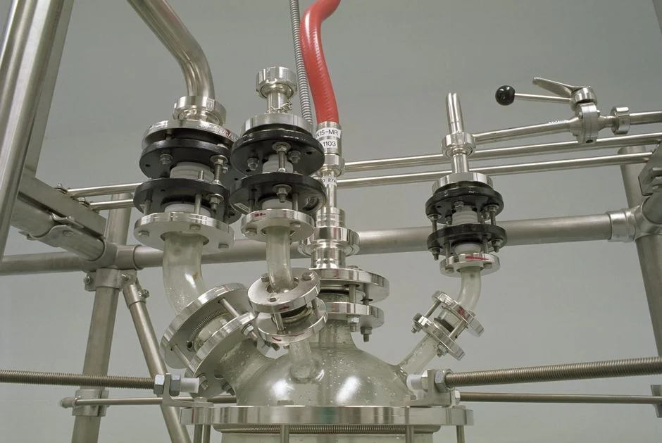
A fixed-bed system is the baseline configuration described by PDH Academy: cylindrical vessels containing resin, with upper and lower manifolds, gravel underdrain, regenerant distributor and air-scour grid (PDH Academy, September 2023). The additional vessels or process stages should solve a defined operating requirement, not merely add equipment.
| Configuration | Appropriate when | Main engineering question |
|---|---|---|
| Single vessel | Interruption during regeneration is acceptable and one treatment step satisfies the objective. | Can treatment be stopped without affecting production, reuse commitments or downstream equipment? |
| Parallel ion exchange vessels | Continuous treatment is important and one vessel must be regenerated while others remain in service. | Does the valve manifold support isolated service, regeneration and rinse modes without unacceptable flow or pressure effects? |
| Staged system | Removal targets or continuity require additional treatment capacity or separation steps. | What measurable contaminant or product-quality step justifies each stage? The supplied research does not provide universal stage-selection rules. |
| Continuous counter-current ion exchange | Resin utilization, throughput and regenerant recovery justify greater control complexity. | Can the site support the additional operating and recovery integration? The University of Cape Town study identified regenerant cost as a major cost item and developed chemical recovery around a five-column CCIX pilot plant (University of Cape Town, 1979). |
| Industrial softener integrated with another process | Hardness removal is required before a downstream treatment step. | Is an industrial twin-tank ion exchange water softener appropriate, or is a general wastewater ion-exchange train required? |
For reverse-osmosis integration, pretreatment must be selected from the feed composition and the downstream membrane requirements, not from a generic equipment label. An industrial reverse osmosis system changes the required pretreatment and makes control of hardness, organics and suspended solids particularly relevant to system configuration.
A paired-brine-tank softener also differs from a general industrial wastewater train. Its alternating vessels, brine regeneration and saline waste route should match the actual hardness-removal duty. If the objective is contaminant recovery, complete deionization or process-water reuse, the softener arrangement may be only one component of the required system.
From Process Diagram to Equipment Specification
A supplier comparison is only meaningful when every proposal uses the same design basis. The request for information should begin with the target contaminant, feed-water matrix, required product-water quality, reuse or discharge destination, operating hours and treatment objective.
The supplier should then define the complete scope. That scope must include pretreatment, service-flow piping, regeneration and rinse piping, standby or parallel capacity where required, controls, instrumentation and regeneration-waste handling. A process-flow drawing that omits the waste route is incomplete because it does not show where the captured contaminant goes.
| Information to request | Why it matters | Acceptance check |
|---|---|---|
| Resin type, operating form and proposed regenerant | Defines selectivity, chemical demand and waste chemistry. | Match the proposal to the contaminant and recovery objective. |
| Regeneration sequence and backwash method | Establishes how the vessel returns to service and how the bed is restored. | Show every service, regeneration, rinse, drain and isolation state. |
| Valve arrangement and vessel configuration | Determines whether continuous service, standby capacity or parallel operation is technically possible. | Trace each permitted valve state without an unintended bypass. |
| Flow, pressure, resin-volume and chemical-consumption data | Connects the diagram to equipment sizing and operating cost. | Obtain project-specific calculations from the supplier; the supplied research supports no universal values. |
| Product-water monitoring and breakthrough criteria | Connects operating decisions to the treatment objective. | Name the measurement, location, action and acceptance criterion. |
| Regenerant and rinse waste balance | Defines collection, segregation, treatment, recovery and final destination. | Require stream-by-stream destinations and state assumptions. |
| Control narrative | Shows how sequence steps, interlocks, alarms and abnormal conditions are managed. | Distinguish automatic functions from operator actions. |
Missing stream balances, waste-routing details and control narratives are procurement risks. The source literature treats contaminant concentration and regenerant recovery as central design issues: Bolto and Pawlowski state that pollutants must be removed in concentrated form to facilitate recovery (Springer Netherlands, 1985), while the University of Cape Town study documented regenerant recovery and dissolved-component concentration in a five-column CCIX pilot plant (University of Cape Town, 1979).
Use the ion exchange valves, tanks, resin and monitoring components schedule only after the process basis is fixed. A parts list cannot resolve an undefined separation objective, incomplete waste route or untested control sequence.
Frequently Asked Questions
What information is required to size an industrial ion exchange system?
Request the complete feed-water analysis, target contaminants, required product-water quality, operating flow and hours, pretreatment basis, regeneration availability, intended waste outlet and reuse or discharge objective. Ask the supplier to provide project-specific flow, pressure, resin-volume and chemical-consumption calculations. The supplied research provides no universal sizing values.
Should the process flow diagram be a PFD or a full P&ID?
Use a PFD for the overall process, service path, regeneration loop and waste destinations. Use a P&ID for procurement when valve states, drains, vents, bypasses, alarms, interlocks and control loops must be verified. PDH Academy (September 2023) describes fixed-bed vessels and operating configurations, but it does not remove the need to define the appropriate drawing level.
How much does an industrial ion exchange system cost?
Request a project-specific quotation covering vessels, resin, pretreatment, valves, regeneration equipment, controls, instrumentation and waste handling. Also request separate operating-cost estimates for resin replacement and regenerant use. No quotation or defensible generic price is supplied by the research, so a budget should not be built from unsupported figures.
Which regenerant should be selected for cation and anion exchange?
Confirm the regenerant against the resin form and contaminant objective. PDH Academy (September 2023) identifies sulfuric or hydrochloric acid for conventional cation regeneration, sodium chloride brine for salt-based softening, and a strongly basic solution such as sodium hydroxide for anion regeneration. Ask for a stream-by-stream waste assessment before approving the chemical.
How should regeneration wastewater be managed for discharge or reuse?
Require the supplier to identify where regenerant and rinse streams originate, how they are segregated, their chemical characteristics, the proposed neutralization or treatment steps, and the final discharge or reuse point. Bolto and Pawlowski emphasize recovery of pollutants in concentrated form (Springer Netherlands, 1985), while the University of Cape Town study demonstrates the role of regenerant recovery and concentration of dissolved feed components (University of Cape Town, 1979).