What Treatment Does a Bikaner Data Center Actually Need?
A Bikaner data center needs treatment designed around its actual cooling system, not one generic wastewater plant. Closed-loop facilities mainly require treatment of sanitary wastewater, leakage, maintenance water and any occasional cooling discharge; evaporative or hybrid facilities also need a dedicated cooling-tower blowdown train. Blowdown contains concentrated salts, suspended matter and residual chemicals, while ordinary brackish RO is commonly limited to 75–80% recovery by scaling constraints. The appropriate train typically progresses from segregation and monitoring to physical removal, biological treatment for sanitary flows, disinfection, and UF or RO where reuse quality justifies them.
Start by determining whether the facility uses closed-loop, evaporative or hybrid cooling. A SIFY-linked post on Indian data-center cooling, published in 2025, reports that the Indian industry has favored closed-loop systems because of water stress and sustainability goals. It gives closed-loop initial pipe-fill demand as 3,000–10,000 liters per MW and subsequent leakage and maintenance demand as 100–1,000 liters per MW per year. These are context figures, not a Bikaner design flow.
IDE states that a 100-megawatt facility can use up to 2 million liters of water per day, but the actual Bikaner requirement must come from the facility design, operating mode and measured water balance. For a broader architectural benchmark, see the detailed data-center blowdown treatment framework and the international data-center cooling-blowdown treatment guide.
| Wastewater stream | Inventory question | Likely treatment duty |
|---|---|---|
| Sanitary wastewater | Continuous or intermittent? | Biological treatment, solids separation and disinfection |
| Cooling-tower blowdown | Continuous or occasional? | Filtration or flotation; additional treatment if reused as cooling make-up |
| Process wastewater | What process and chemicals are present? | Stream-specific removal or controlled segregation |
| Equipment washwater | Does it contain cleaners, oil or disinfectants? | Local collection and contaminant-specific treatment |
| Firewater | Is there a fire-water retention requirement? | Contingency storage; normally excluded from routine treatment |
| Laboratory wastewater | Which assays and reagents are used? | Separate collection and compatible treatment |
| Stormwater contamination | Which drains can receive runoff or spills? | Isolation, inspection and spill-response controls |
The decision rule is straightforward: establish whether blowdown is continuous or occasional, then assign each stream to its destination—cooling make-up, sanitary reuse, washwater, irrigation or authorized discharge. Treatment should follow that assignment, not precede it.
Build a Bikaner Water Balance Before Choosing Equipment
Equipment should be sized from measured flows and water chemistry, not from facility megawatts or a vendor’s nominal treatment rate. Genesis Water Technologies recommends metering make-up water, blowdown, evaporation, leakage, maintenance use and final discharge. It also recommends monitoring conductivity, pH and suspended solids with the flow measurements.
For a steady cooling tower, the theoretical blowdown ratio is 1/(CoC−1). Genesis reports that 4 cycles of concentration corresponds to 25% blowdown and 6 CoC to 20%. Moving from 4 to 6 CoC therefore reduces blowdown by five percentage points, or 20% of the 4-CoC blowdown volume—not 50%. The same source reports actual blowdown can exceed theoretical calculations by 15–30% because of unmeasured losses and emergency dumps.
Do not confuse site water usage with consumption. Genesis defines WUE as annual site water usage divided by IT equipment energy. Consumption includes water removed through evaporation or incorporation into products, while usage also includes water withdrawn and returned after treatment. WUE alone does not show discharge quality, evaporation, or reuse potential, so it should not determine treatment capacity.
| Water-balance item | Required measurement | Decision supported |
|---|---|---|
| Cooling make-up | Continuous flow and volume | Freshwater demand and potential recovery target |
| Blowdown | Flow, chemistry and operating duration | Physical and membrane pretreatment sizing |
| Evaporation | Calculated from the operating water balance and verified | True consumptive loss |
| Leakage and maintenance | Event records and metered use | Closed-loop treatment and contingency storage |
| Final discharge | Flow, temperature and quality | Discharge route and reuse allocation |
| Recovered water | Flow and destination-specific quality | Real water-saving benefit and reticulation demand |
Before final sizing, verify Bikaner source-water quality and seasonal variation, electricity reliability, available reuse destinations, sewer or discharge route, and current conditions imposed by the relevant Bikaner authorities. The supplied research does not establish a Bikaner source-water analysis or local discharge limits, so those remain project inputs rather than assumptions.
Segregate Wastewater by Contaminant and Treatment Duty
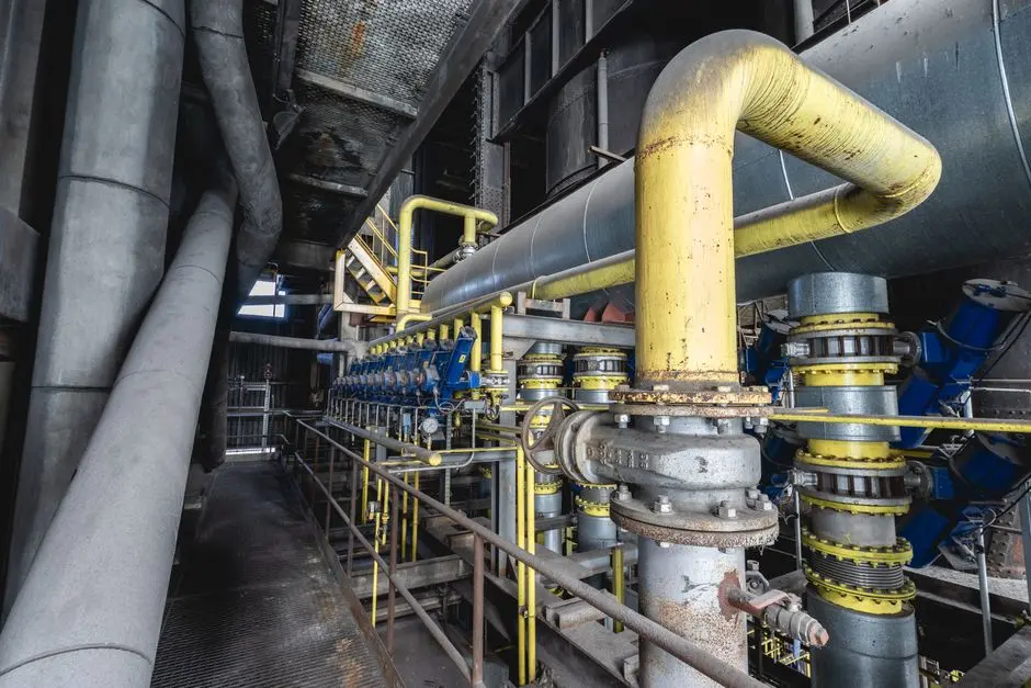
Sanitary wastewater should remain separate from cooling and process wastewater because the required biological, chemical and disinfection duties differ. Combining them can increase organic loading, suspended solids, salt concentration and treatment complexity. A segregated MBR system for segregated sanitary wastewater can address the sanitary duty without exposing every reuse stream to biological solids.
Cooling blowdown has a different contaminant profile. IDE describes it as a brackish stream enriched with sparingly soluble salts, including silica, calcium carbonate and calcium sulfate. It also contains suspended matter and residual treatment chemicals. These constituents determine whether filtration is sufficient, whether RO is technically viable, and whether precipitation or another controlled salt-management step is required.
Storm drains, firewater and equipment washwater need isolation because intermittent, high-strength flows can overload a continuously operated treatment train. Equalization is therefore a compatibility control, not a default treatment step. Required detention and storage must follow the actual flow survey, batch size, chemistry and permitted operating strategy.
| Stream | Primary contaminants or risks | Segregation control | Treatment decision |
|---|---|---|---|
| Sanitary wastewater | Organic matter, nutrients and pathogens | Keep separate from cooling and process streams | Biological treatment, solids separation and disinfection |
| Cooling blowdown | Dissolved salts, scaling compounds, suspended solids and residual chemicals | Dedicated collection and conductivity monitoring | Physical removal first; UF or RO only against a defined reuse specification |
| Process wastewater | Process-specific chemicals and variable concentrations | Batch collection and incompatibility review | Targeted treatment based on complete analysis |
| Equipment washwater | Cleaners, oil, suspended solids or disinfectants | Do not combine with continuous reuse flow | Local treatment or controlled discharge |
| Firewater and storm runoff | Intermittent contamination and potentially high pollutant loads | Physical isolation and spill-response controls | Exclude from routine treatment unless contamination is confirmed |
Genesis specifically identifies conductivity, pH and suspended solids as monitoring points alongside flow. For a scaling-sensitive blowdown route, hardness, silica and scaling indicators should also be included when the proposed process requires them. This location-specific data-center wastewater planning illustrates the broader need to map streams and destinations before selecting a plant.
Select the Treatment Train by Reuse Destination
The reuse destination sets the required water quality, so a single “treated blowdown” specification is not enough. Genesis recommends physical separation such as media filtration or dissolved-air flotation followed by treatment for identified contaminants. It states that reusing treated blowdown for non-critical process water can reduce make-up demand by 15–25%. That route may support washwater or other approved non-critical uses, but it does not automatically qualify the water for cooling make-up.
For sanitary reuse, the biological route must address organic load and pathogens before discharge or reuse. The catalogued MBR system for segregated sanitary wastewater handles 10–2,000 m³/day and is specified to produce effluent below 1 micron, described as near-reuse quality. Flow capacity must still be matched to the Bikaner sanitary duty.
Cooling make-up requires more than clear permeate. The receiving tower’s specifications must cover conductivity, hardness, silica, suspended solids, residual treatment chemicals and microbiological activity. IDE’s industrial example demonstrates the difference between recovery and usable quality: its brine desalter operated at around 95% recovery and reduced permeate silica to about 1 mg/L. That configuration used controlled salt removal; a generic 95% recovery claim does not reproduce the same result.
Ultrafiltration can protect downstream RO from colloids, bacteria and suspended solids. The supplied UF pretreatment for data-center reuse water uses 0.03-micron PVDF membranes, accepts up to 300 ppm turbidity and has a stated flow span of 2,000–40,000 L/h. The multi-media pretreatment for RO protection is the relevant solids-removal option where lower-complexity pretreatment is sufficient.
| Reuse destination | Indicative treatment sequence | Critical acceptance checks | Main constraint |
|---|---|---|---|
| Washwater or non-critical process use | Equalization as needed; media filtration or flotation; targeted contaminant removal | Suspended solids, pH and contaminants relevant to the receiving process | Reuse must fit the equipment and worker-exposure requirements |
| Sanitary reuse | Biological treatment; membrane solids separation; disinfection | Organic treatment, solids, pathogen control and applicable reuse criteria | Do not blend with cooling blowdown before biological treatment |
| Cooling make-up | Filtration; optional UF; controlled RO; post-treatment and disinfection as required | Conductivity, hardness, silica, scaling indices, residual chemicals and microbiological activity | Salt concentration and scaling can limit recovery |
| Authorized discharge | Only the treatment necessary for the receiving-system and permit requirements | Current authority conditions, receiving-system limits, temperature and discharge quality | Specific Bikaner limits were not supplied and must be verified |
For cooling make-up, the industrial RO system for cooling-water recovery is a candidate when automated permeate production and recovery rates up to 95% are commercially justified. However, IDE reports that conventional brackish-water RO commonly plateaus at 75–80% recovery because scaling becomes difficult to manage. Any higher-recovery proposal must be validated against actual Bikaner source and blowdown chemistry, not a generic product rating.
Protect Equipment, Staff and Downstream Water Quality
Equipment protection begins with pretreatment acceptance criteria derived from the selected membrane or filter. The multi-media filter is intended to produce an SDI suitable for downstream RO protection; that objective is more useful than an unsupported generic turbidity limit. UF may be justified where the required solids removal and downstream protection cannot reliably be met by media filtration alone.
Monitoring should cover conductivity, pH and suspended solids as established by Genesis, with hardness, silica and scaling indices added when the reuse train requires them. Numeric acceptance limits must come from the cooling make-up specification, actual blowdown chemistry and OEM water-quality limits; they should not be invented during tender evaluation.
Disinfection and residual control must precede reuse into a cooling loop or any potable-connected process. The supplied chlorine dioxide generator is listed at 50–20,000 g/h for industrial cooling loops and process wastewater. Its application still requires compatibility testing with the cooling chemistry, materials, dosing arrangement and downstream residual requirements.
| Checkpoint | Information required | Engineering response |
|---|---|---|
| Feed-water acceptance | Flow range, conductivity, suspended solids, turbidity, hardness, silica and residual chemicals | Set treatment and reject limits before selecting equipment |
| Filter and membrane protection | Target SDI or other manufacturer-specific criterion | Confirm pretreatment duty and automatic backwash operation |
| Chemical control | pH range, antiscalant need and residual limits | Use an automatic chemical dosing system for pH control where justified; avoid unnecessary dosing |
| Microbiological control | Receiving-system specification and contact or residual criteria | Validate the disinfection process before reuse |
| Normal operation | Trend data for flow, pressure, conductivity, pH and cleaning triggers | Configure alarms and controlled operating envelopes |
Prepare responses for power loss, high conductivity, membrane differential-pressure rise and unexpected biological load. Genesis emphasizes operational simplicity for facilities that do not have hyperscale staffing, so automatic controls, clear alarm logic and maintainable equipment matter. The design should also include safe bypass, hold-up and sampling arrangements that do not silently route untreated water to a reuse destination.
Implement Treatment in Stages and Verify Performance
Implementation should follow the five-stage sequence in Genesis Water Technologies: measurement and baseline; optimization of existing systems; chemical-program review; blowdown treatment and reuse; and advanced integration for make-up reuse. This sequence reduces the risk of installing a large plant while leakage, once-through cooling or premature blowdown controls remain unresolved.
Before adding treatment capacity, repair leaks, eliminate unnecessary once-through cooling, optimize cooling control sequences and provide effective self-cleaning filtration. Then establish whether the recovered water has a defined non-critical reuse or whether the project must meet cooling make-up quality from the start.
Pilot the selected train using site water. Neither a modular equipment rating nor industrial reference performance substitutes for Bikaner source-water and blowdown characterization. During the pilot, confirm removal of identified contaminants, membrane recovery, chemical demand, cleaning frequency, energy consumption and operability under the facility’s actual staffing model.
Genesis provides a modular treatment example of 100–300 GPM. Treat that as a scale reference, not a required Bikaner size. Equipment and membranes should be selected from measured flow and the verified duty; the RO and UF membrane and filter elements should likewise be matched to the validated process and change-out strategy.
Verify performance against the intended reuse specification, not simply against outlet clarity. Track site water use, actual consumption, final discharge, chemical use, energy use, membrane recovery, maintenance labor and recovered-water availability. Stage capital expenditure so that lower-complexity reuse can demonstrate savings before advanced cooling make-up recovery is funded. The capital gate should be based on measured avoided freshwater and disposal costs, not WUE alone.
Questions to Ask Before Ordering a Bikaner Treatment Plant

A supplier should size the plant from measured flows and a complete water analysis, not from facility MW alone. The tender should identify the source, seasonal range, expected duration of each stream, reuse destination, required water quality and recovery basis. Ask the supplier to state what feed-water ranges its guarantee covers and whether flow variations or emergency dumps are included.
Require performance guarantees for the intended duty: recovered-water quality, recovery percentage, availability, energy and chemical assumptions, and the documents supporting each claim. The supplier should explain how silica, calcium carbonate and calcium sulfate scaling will be controlled and whether a pilot test using representative Bikaner water is included.
Also ask about PLC controls, automatic backwash, membrane-cleaning strategy, spare-parts availability, operator training and local service support. These are operational requirements, not optional features. The supplier should separate base treatment, optional RO recovery, reuse reticulation, disposal and installation costs so lifecycle economics can be compared without hidden scope assumptions.
Finally, require written confirmation that the discharge or sewer connection will be designed around current Bikaner permits and receiving-system conditions. The supplied research provides no specific Bikaner discharge limits, so a proposal should identify the authority requirements as an owner-provided input rather than bury them inside a performance guarantee. Related procurement lessons are available in the Zagreb data-center treatment procurement review and the Calumbo data-center treatment comparison.
Frequently Asked Questions
How much does wastewater and cooling blowdown treatment cost for a Bikaner data center?
There is no defensible Bikaner price without a measured flow and source-water analysis. Request a capital and operating breakdown that separately prices pretreatment, optional RO recovery, reuse piping, disposal, chemicals, energy, solids handling and installation. Compare the result against avoided freshwater and disposal costs using the facility’s actual tariffs and operating profile.
How should a Bikaner data-center treatment system be sized?
Size it from measured stream flows, duration, chemistry and reuse quality. The closed-loop figures of 3,000–10,000 liters per MW for initial filling and 100–1,000 liters per MW per year for leakage and maintenance, reported by the SIFY-linked 2025 post, provide context only; they do not establish the design flow. A continuous blowdown train and an occasional discharge require different sizing and storage assumptions.
How should a treatment-equipment supplier be selected?
Require site-specific guarantees, pilot evidence, control narratives, service capability, membrane or filter data and transparent scope boundaries. Check whether the proposed guarantee covers seasonal feed variation, recovery basis, cleaning frequency and unattended operation. A supplier should explain what it does not guarantee, especially around scaling and reuse availability.
Does a closed-loop data center need cooling-tower blowdown treatment?
Not if the facility has no cooling tower or other continuous evaporative blowdown stream. It still needs a treatment plan for sanitary wastewater, leakage, maintenance water and any equipment washwater, with each flow assigned to a destination. Confirm the installed cooling architecture rather than assuming that a closed-loop designation applies to every heat-rejection component.
What discharge permits and reuse approvals apply in Bikaner?
Verify current requirements with the relevant Bikaner authorities and receiving sewer or discharge system. The treatment train should be based on those written conditions, including any temperature, water-quality, reuse and monitoring obligations. The supplied research does not provide specific Bikaner discharge limits, so no numerical compliance claim should be made until they are confirmed. For wider stream-planning context, see the location-specific wastewater framework and the Sagamihara blowdown-treatment review.