Separate the Data Center’s Wastewater Streams Before Selecting Equipment
A Zagreb data center should separate cooling tower blowdown from sanitary sewage before selecting treatment equipment because they have different chemistry, disposal routes and approval requirements. Cooling blowdown is formed when evaporation leaves dissolved minerals and treatment chemicals behind in the circulating water; it is not ordinary fresh water or domestic sewage. Treatment may require equalization, solids removal, pH adjustment and chemical conditioning before discharge, or additional polishing for cooling-tower makeup reuse. Final equipment selection depends on measured peak blowdown, complete water chemistry, the cooling system’s cycles of concentration, local discharge acceptance and the available plant footprint.
RSP Engineers identifies cooling tower blowdown as the primary process-wastewater stream in most large data centers. Sanitary sewage should remain on the domestic route, while blowdown, reverse-osmosis reject, softener backwash, equipment-cleaning wastewater and air-handling condensate require separate assessment. Their flows and contaminants must not be averaged into one design flow.
Scale makes early separation essential. IDE Tech’s published example states that a 100-megawatt data center can use up to 2 million liters of water per day; this is an illustrative facility benchmark, not a prediction for Zagreb. Even if blowdown represents a modest percentage of that total, a continuous stream can require a substantial equalization and treatment train.
| Stream | Defining characteristics | Design implication |
|---|---|---|
| Sanitary sewage | Restroom and kitchen waste | Domestic sewer route; separate from process-water treatment |
| Cooling tower blowdown | Concentrated minerals, suspended solids and cooling chemicals | Process treatment, permit review and possible reuse train |
| RO reject | Concentrated salts removed from feedwater | Separate concentrate-management decision |
| Softener backwash | Regeneration waste containing exchanged ions and treatment chemicals | Characterize independently before combining |
| Equipment-cleaning wastewater | Variable chemistry and flow depending on cleaning agents | Segregate and collect for controlled treatment |
| Air-handling condensate | Condensed water with possible contamination | Confirm quality and disposal or reuse eligibility |
Before sizing, request a site water-balance diagram showing cooling makeup water, evaporation, blowdown, reuse, discharge, storage and emergency dumps. The engineering basis should also distinguish continuous flow from intermittent operating events. Further stream-by-stream treatment considerations are set out in this data-center cooling blowdown treatment guide.
Characterize the Blowdown Chemistry That Drives Treatment
Cooling blowdown chemistry determines whether the stream can be discharged with limited pretreatment or requires membrane and advanced treatment. Source-water analysis is not a substitute for sampling the actual cooling circuit because evaporation concentrates dissolved constituents and the cooling program adds its own chemical load.
Complete the analytical program across representative operating and seasonal conditions. Test conductivity, total dissolved solids, pH, suspended solids, temperature, calcium, hardness, alkalinity, silica, sulfate, chloride, phosphate, residual biocides and corrosion-inhibitor ingredients. Document the cooling system’s cycles of concentration and the complete chemical package, including dosing products, concentrations and rotation schedules. Samples should represent normal operation and relevant events such as chemical rotations, high-load periods and emergency blowdown.
RSP Engineers reports that blowdown may contain elevated TDS, chlorides, sulfates, phosphates, biocides, corrosion inhibitors and scale-control agents. These constituents affect both sewer acceptance and downstream treatment. Suspended solids can foul membranes, silica can constrain recovery, and residual biocides can influence biological treatment or disinfection requirements. Complete chemical disclosure is therefore necessary before selecting equipment.
| Parameter or input | Engineering question | Effect on treatment selection |
|---|---|---|
| Conductivity and TDS | How concentrated is the cooling loop? | Establishes desalination load and concentrate volume |
| pH, alkalinity, calcium and hardness | Can the stream be neutralized without excessive chemical use? | Determines dosing and precipitation risk |
| Silica | What concentration reaches the membrane system? | Controls scaling limits and achievable recovery |
| Sulfate, chloride, phosphate and TDS | Which dissolved salts must be removed or monitored? | Influences permit basis and RO concentrate chemistry |
| Suspended solids | How much material must be removed before sensitive equipment? | Sets equalization, clarification and filtration requirements |
| Biocide and inhibitor ingredients | What active products and residual concentrations are present? | Defines discharge controls and reuse compatibility |
| Temperature | Will cooling or holding be needed before discharge? | Affects equalization storage and receiving-system acceptance |
IDE Tech identifies silica, calcium carbonate and calcium sulfate as sparingly soluble salts that constrain cooling tower blowdown recovery. These compounds can reach scaling thresholds as evaporation concentrates the circulating water. A full chemistry assessment also supports treatment selection in the context of this cooling-blowdown chemistry guide for data centers.
RSP Engineers gives a 150°F discharge-temperature limit as a US example. It is not a Zagreb legal limit. Temperature acceptance must be confirmed with the relevant Croatian and Zagreb authorities, together with any sewer or wastewater operator requirements.
Match the Treatment Objective to Zagreb’s Discharge and Reuse Options
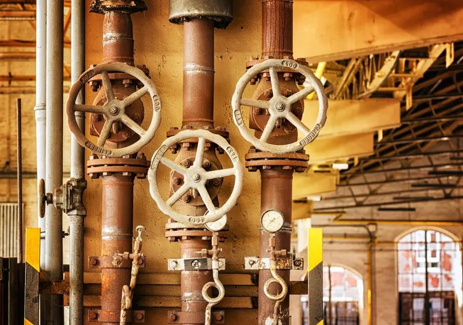
The treatment objective determines the equipment: sewer discharge, lower-grade reuse and cooling-tower makeup reuse have different quality, monitoring and residual-management requirements. A single treatment train should not be selected before those uses are defined.
For a discharge-led route, start with equalization and cooling where required, pH adjustment, removal of suspended solids and treatment for chemical constituents identified by the receiving authority. RSP Engineers gives pH adjustment in the 6.0–9.0 range as an industry example only; the enforceable requirement must come from the Croatian environmental authority, Zagreb sewer authority or other competent authority.
For partial reuse, consider equipment washing, dust control or irrigation only after confirming local and site-specific acceptability. This route may require less polishing than cooling-tower makeup, but it still needs a defined quality standard, distribution arrangement and approval. Do not assume that a non-potable use removes the need to control the discharge route or protect public and site workers.
For cooling-tower makeup reuse, IDE Tech identifies reverse osmosis followed by chemistry-aware treatment as a route to high-quality recycled water. Its high-recovery concept combines RO with controlled precipitation of scaling salts and dynamic membrane operation. This addresses the limitation of conventional brackish-water RO: IDE Tech reports that conventional systems typically reach 75–80% recovery before scaling becomes difficult to manage.
| Decision factor | Discharge-led treatment | Lower-grade partial reuse | Cooling-tower makeup reuse |
|---|---|---|---|
| Primary objective | Meet confirmed discharge acceptance conditions | Replace selected freshwater uses | Reduce cooling makeup demand |
| Typical treatment emphasis | Equalization, pH control, solids removal and targeted chemical treatment | Solids removal and application-specific polishing | Comprehensive pretreatment, RO and chemistry management |
| Compliance exposure | Concentrated discharge remains the principal permit issue | Both reuse approval and residual discharge must be managed | Water quality, cooling-system integrity and concentrate disposal all require control |
| Operational burden | Chemical dosing, sampling and discharge monitoring | Application controls and water-quality verification | Higher monitoring and membrane-operation demands |
| Residual handling | Sludge or precipitated solids from pretreatment | Concentrated residual plus application-site controls | RO concentrate and any precipitated solids |
| Footprint and complexity | Generally lowest for limited pretreatment | Depends on storage, distribution and treatment quality | Highest because of pretreatment, RO, storage and residual management |
Genesis Water Technologies proposes a staged roadmap: measurement and baseline; existing-system optimization; review of chemical treatment; blowdown treatment and reuse; then advanced integration. That sequence prevents premature equipment overdesign. It also helps determine whether leakage control, control-sequence changes or chemical review can reduce blowdown before a treatment skid is purchased. A European perspective is available in this European data-center blowdown treatment guide.
Build a Pretreatment and Advanced-Treatment Process Train
A defensible treatment train removes solids and controls chemistry before sensitive membranes or reuse equipment. Equalization precedes treatment to buffer variable flow and loads; solids removal precedes filtration or RO; chemical conditioning is applied where analysis demonstrates a need; and storage or disinfection is added only when required by the intended reuse.
Equalization also provides the hydraulic buffer needed for controlled dosing, maintenance access and upset response. Removal of suspended solids before RO reduces membrane fouling and prevents retained solids from entering downstream storage or cooling makeup.
For sites requiring dissolved solids or oil and grease removal, an industrial DAF system for cooling blowdown pretreatment can provide physical separation. HydropureWater’s published DAF range covers 4–300 m³/h across 13 models and is described as removing suspended solids, FOG, oil and grease, and colloidal matter. These are product specifications, not a Zagreb flow selection; the applicable model must be selected from measured peak flow and analysis.
Ultrafiltration is another pretreatment option where membrane performance is needed before sensitive reuse applications. HydropureWater’s published UF range uses 0.03 μm PVDF membranes, handles 2,000–40,000 L/h, and is described as removing bacteria, colloids and suspended solids without chemicals. Whether that specification suits the actual stream depends on feed chemistry, temperature, flow and required permeate quality.
Use PLC-controlled chemical dosing for pH adjustment, coagulation or flocculation only after the analysis demonstrates the need. Excess chemical addition raises operating cost, increases dissolved solids and can complicate downstream RO or sewer acceptance. The automatic chemical dosing system should therefore be specified from control requirements, chemical inventory, containment and dosing capacity—not from a generic treatment-package template.
Position industrial RO where permeate quality and feed chemistry justify it. HydropureWater specifies recovery rates up to 95%, but project recovery must be established from complete feed analysis, scaling calculations and pilot work or a vendor performance guarantee. The industrial RO system for cooling-tower makeup reuse must also address post-treatment, storage, biological control, membrane cleaning and concentrate disposal.
| Process step | Primary purpose | Design input |
|---|---|---|
| Equalization | Buffer peak flow and treatment loading | Hourly flow, operating sequence and storage time |
| Solids removal | Reduce suspended solids, colloids and relevant floatables | Solids loading, particle characteristics and required quality |
| Chemical conditioning | Adjust pH or target identified contaminants | Complete chemistry and receiving-water requirements |
| Filtration or RO | Prepare water for the selected reuse route | Feed analysis, scaling, recovery and fouling risk |
| Polishing and storage | Meet reuse quality and buffer distribution demand | Permeate specification, storage and turnover |
| Residual management | Control concentrate, sludge and precipitated solids | Residual chemistry, quantity and accepted disposal route |
The practical sequence is equalization → solids removal → chemical conditioning → filtration or RO where appropriate → polishing and storage → reuse or permitted discharge.
Calculate the Water Balance and Size the Treatment Plant

Measured flows must determine treatment capacity; theoretical cooling equations are only the starting point. Genesis Water Technologies reports that actual blowdown can exceed theoretical calculations by 15–30% because of unmeasured losses and emergency dumps. Install or verify metering for makeup water, evaporation, blowdown, reuse and discharge before finalizing equipment.
The cooling cycles-of-concentration relationship provides an initial check. Genesis gives the blowdown ratio as 1 divided by cycles of concentration minus one: at 4 cycles, blowdown is 25% of makeup volume; at 6 cycles, it is 20%. The move from 4 to 6 cycles therefore reduces blowdown by five percentage points of makeup volume, not by the 50% sometimes assumed.
Size equalization, DAF, UF, RO, pumps and storage against peak blowdown and the intended operating strategy. Average daily intake will understate equipment demand and may hide emergency-dump or maintenance conditions. Confirm whether storage is intended to level peaks, cover outages or both.
| Sizing input | Why it matters | Evidence required |
|---|---|---|
| Peak blowdown flow | Governs hydraulic treatment capacity | Time-series meter data and operating scenarios |
| Daily and annual flow | Supports chemical use, utilities, labor and lifecycle costing | Validated water balance and operating history |
| Cycles of concentration | Determines concentration and blowdown relationship | Cooling design, controls and measured chemistry |
| Recovery target | Determines RO feed, permeate and concentrate rates | Complete feed analysis, reuse target and pilot data |
| Equalization requirement | Controls treatment variability and downtime response | Peak-flow profile and operating philosophy |
| Residual route | Affects pumps, storage, logistics and site footprint | Written acceptance and residual quantity estimate |
Genesis cites a modular 100–300 GPM blowdown treatment system as an industry reference, not a Zagreb requirement. Convert flow only after confirming the project’s units and measured duty. A system capable of average flow can still be undersized if it cannot handle a sustained peak or an emergency discharge.
Reserve civil space for the treatment skid, chemical storage containment, drainage, maintenance access, sample points, monitoring equipment and future expansion. RSP Engineers reports that a simple pH-neutralization system may occupy several hundred square feet, while filtration plus chemical precipitation may require several thousand square feet. These are US planning examples, not guaranteed Zagreb footprints; the project design still requires supplier dimensions and a site-specific layout.
Plan Zagreb Permitting, Utilities and Operational Controls
Early authority coordination is necessary because sewer acceptance can change the treatment train after equipment selection. Engage the relevant Croatian environmental authority, water supplier and Zagreb sewer or wastewater authority to establish the lawful discharge route, industrial-user conditions, monitoring duties and reporting requirements.
Do not transfer a US sanitary-sewer or NPDES framework directly into a Croatian project. The pathways described by RSP Engineers are US engineering precedents. For Zagreb, the enforceable framework must be confirmed with the competent Croatian and municipal bodies, including any conditions for connecting process wastewater to the sewer.
Before freezing the design, request written confirmation of limits for pH, temperature, conductivity, suspended solids, flow, chemical constituents, toxicity and sewer acceptance. The written conditions should also address monitoring frequency, sampling methods, composite sampling, emergency limits and consequences of non-compliance.
Provide automatic monitoring and alarms where required, sampling ports, laboratory access, spare chemical capacity, bypass controls and a documented upset-response plan. The control narrative should define what happens during high flow, chemical-inventory shortage, power loss, membrane-fouling indication, abnormal pH and unavailable residual-disposal capacity.
Assign ownership for residual brine, sludge and precipitated solids, and obtain written acceptance for their disposal route. A treatment train is not complete until the residual stream has a technically and legally available destination. The wider planning basis is covered in this data-center cooling-blowdown planning guide.
Track WUE, but do not rely on it alone. Genesis explains that WUE is annual site water usage divided by IT equipment energy and does not distinguish consumption from water that is withdrawn, used and returned after treatment. Report actual consumption, freshwater withdrawal, reuse and discharge separately so that recycling and true consumption are not presented as equivalent outcomes.
Use a Procurement Checklist to Compare Equipment Bids
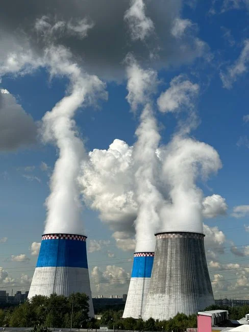
A comparable bid must state guaranteed process performance, not only equipment price and nominal capacity. Require the vendor to commit to feed flow, permeate flow, overall recovery, treated-water quality, concentrate volume, utility demand, footprint and operating availability. Define guarantees around the project’s measured feed conditions and accepted sample points.
Ask vendors to document silica and calcium scaling controls, membrane fouling management, chemical consumption, automatic backwash, controls, alarms, remote monitoring and operator workload. The response should identify assumptions that could invalidate the guarantee.
| Bid package | Required evidence | Acceptance point |
|---|---|---|
| Process design | Complete P&ID, equipment list, water balance and control narrative | Matches measured Zagreb flows, chemistry and selected reuse route |
| Performance | Guaranteed flow, quality, recovery, availability and concentrate quantity | Defined by site-specific feed analysis and performance test |
| Operations | Commissioning protocol, maintenance plan, consumables and training | Feasible for site staffing and access arrangements |
| Commercial | Warranty scope and local technical-support model | Responsibility and response path are contractually defined |
| Lifecycle cost | Water, disposal, chemicals, energy, labor, monitoring and residual handling | Compared on the same flow, chemistry and utilization basis |
Compare lifecycle cost rather than purchase price alone. Require a site-specific feed-water analysis and an acceptable performance test; reject generic recovery or capacity claims that do not apply to the actual blowdown. A high-capacity industrial wastewater treatment guide provides a useful reference for the documentation expected from an experienced bidder.
Frequently Asked Questions
What inputs are needed to estimate the cost of Zagreb data-center cooling blowdown treatment?
Request a project-specific cost estimate based on measured peak blowdown, complete water chemistry, required reuse quality, confirmed disposal route, available utilities and treatment-plant footprint. The estimate should separate equipment, civil works, chemical storage, controls, utilities, labor, monitoring and residual disposal. No supported research source provides a Zagreb price range, so a defensible quotation cannot be produced without those inputs.
How should a supplier be selected for a cooling-tower reuse system?
Require guaranteed process performance, a complete P&ID, an explicit control narrative and a defined local service scope. Check that the supplier has addressed the actual feed chemistry, scaling risk, membrane fouling, concentrate route and performance test. Also compare operating availability and operator workload, not just purchase price.
Should treatment capacity be based on average water use or peak blowdown?
Base hydraulic capacity on measured peak blowdown and the required operating strategy, including storage and emergency conditions. Recovery rate is a separate parameter: it describes the proportion of feedwater recovered as product, not the flow the treatment train can handle. Average intake can therefore leave the system undersized.
What compliance questions must be answered before the Zagreb design is frozen?
Obtain written confirmation from the relevant Croatian and Zagreb authorities regarding the lawful discharge route, sewer acceptance, pH, temperature, conductivity, suspended solids, chemical constituents, flow, monitoring and reporting. Confirm the disposal route for residual brine, sludge and precipitated solids before ordering equipment, because these conditions can change the selected process.