What Treatment Does a Shizuoka Data Center Actually Need?
A Shizuoka data center generally needs source-separated treatment: physical pretreatment for cooling-tower blowdown, chemical control where the cooling-water chemistry requires it, and filtration or membrane polishing only where reuse quality requires it, with sanitary wastewater managed separately. Genesis Water Technologies reports that 20–40% of cooling intake may leave as blowdown; its theoretical blowdown ratio is 25% of makeup water at 4 cycles of concentration and 20% at 6. The final concept depends on Shizuoka source-water chemistry, cooling cycles of concentration, measured water balance, reuse application, facility scale, and current discharge authorization—not on WUE alone.
Start by separating cooling-tower blowdown, sanitary sewage, equipment washdown, and any process wastewater. They have different contaminants, destinations, and treatment duties. Combining them without confirming the receiving sewer’s treatment capacity can move the problem rather than solve it, particularly if washdown introduces cleaning chemicals into a stream intended for cooling reuse.
Cooling blowdown is normally the principal recovery opportunity because it is continuous, already conditioned, and paid for as treated makeup water. Genesis distinguishes water consumption—water removed through evaporation or incorporation—from broader water usage, which includes water returned to the source. A favorable WUE result therefore does not disclose discharge quality, actual consumptive loss, or reuse potential.
The concept cannot be fixed from a generic technology list. Cooling architecture, makeup source, cycles of concentration, chemical program, flow variability, reuse destination, expansion plan, and Shizuoka’s permitted discharge route determine the appropriate train. The data-center wastewater treatment planning framework provides a useful generic starting point, while cooling blowdown treatment guidance for another Japanese municipality illustrates why local data must replace assumptions.
Map the Water Balance Before Choosing Equipment
Measured flows determine the treatment duty; theoretical blowdown alone understates the equipment load. Genesis Water Technologies reports that actual blowdown can exceed theoretical calculations by 15–30% because of unmeasured losses and emergency dumps, so preliminary sizing must reconcile meter data, operating logs, and temporary discharges.
Install or verify metering for makeup water, blowdown, evaporation, and wastewater flows. Genesis also recommends conductivity, pH, and suspended-solids monitoring as part of the baseline. These measurements reveal whether a low WUE score reflects genuine consumption reduction, temporary storage, or water returned through an inadequately characterized discharge route.
| Design input | Evidence or required site information | Procurement consequence |
|---|---|---|
| Cooling cycles of concentration | Genesis gives theoretical blowdown as 1/(CoC−1) of makeup volume: 25% at 4 CoC and 20% at 6 CoC. | Set the preliminary hydraulic duty from the operating CoC, then check it against measured blowdown. |
| Measured blowdown | Genesis reports actual blowdown may exceed theoretical calculations by 15–30%. | Size treatment and equalization from measured peaks and dumps, not only the formula. |
| Water chemistry | Analyze conductivity, pH, hardness, alkalinity, silica, calcium, chloride, sulfate, suspended solids, and temperature. | Define scaling, corrosion, solids, and membrane pretreatment duties. |
| Chemical program | Record biocides, corrosion inhibitors, scale inhibitors, antiscalants, pH adjusters, and feed rates. | Determine whether dosing is required upstream of separation or reuse equipment. |
Moving from 4 to 6 CoC reduces theoretical blowdown from 25% to 20% of makeup water—a 20% reduction, not 50%. Genesis also states that biological and scaling risks increase substantially above 5–6 CoC without advanced treatment. A higher CoC target must therefore be coordinated with cooling-water chemistry, filtration, control logic, and operator capability; it cannot be adopted as an isolated water-saving instruction.
Structure the business case with the same discipline. Genesis describes an illustrative 15 MW facility recovering 60% of blowdown, or 3 million gallons annually, but that example is not a Shizuoka flow estimate. The site team should insert its own measured makeup rate, recovered fraction, operating profile, water price, discharge cost, and treatment costs. An automatic chemical dosing system may be justified by pH or coagulation needs, but it should not be selected until the active chemical program and receiving-water constraints are known. Additional dosing logic is covered in this chemical-dosing guide.
Characterize Cooling Blowdown and Sanitary Wastewater
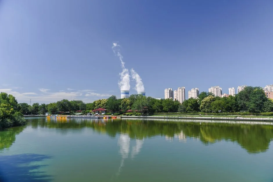
Cooling blowdown is concentrated wastewater, while sanitary sewage requires a separate treatment and acceptance assessment. Water Utility Report lists concentrated dissolved solids, heavy metals, biocides, corrosion inhibitors, altered pH, and other treatment-chemical residues among possible blowdown constituents; the exact profile depends on source water, treatment chemicals, and operating cycles of concentration.
Evaporation removes water while dissolved material remains. The remaining water therefore carries a higher concentration of salts and treatment chemicals than the original source. The engineering consequence is not simply “dirty water”: the blowdown must be characterized against the specific failure mode of its destination. A reuse stream entering a cooling loop must control scale, corrosion, microbiology, and suspended solids; a sanitary discharge route has different acceptance criteria.
| Stream | Principal characterization | Treatment decision |
|---|---|---|
| Cooling-tower blowdown | Dissolved solids, suspended matter, residual treatment chemicals, pH changes, and possible metals | Assess for physical separation, chemistry control, and polishing needed by the selected reuse or discharge route |
| Sanitary sewage | Organics, nutrients, temperature, solids, and cleaning-chemical contributions | Keep outside the cooling-blowdown train; assess under applicable Japanese local requirements and sewer acceptance criteria |
| Equipment washdown | Suspended solids and variable cleaning chemicals; duration may be intermittent or batch | Assess separately and determine whether equalization or dedicated collection is needed |
| Process wastewater | Site-specific contaminants and flow pattern | Characterize before deciding whether it can join either treatment train |
Sample each stream independently. Temperature, organics, nutrients, and cleaning chemicals can change treatment performance and invalidate reuse decisions if streams are blended without evidence. The supplied research does not quantify Shizuoka sewer acceptance criteria, so the buyer must obtain the current requirements from the responsible authority rather than assume that dilute discharge is acceptable.
For sanitary wastewater, use the applicable local route as the starting point. The domestic sewage treatment buyer guide outlines the screening questions, while the underground integrated sewage treatment system represents the type of equipment that may be screened after the flow and acceptance basis are established. Neither product nor route should be selected from flow volume alone.
Build a Shizuoka-Specific Treatment and Reuse Route
A defensible Shizuoka concept begins with source separation: cooling blowdown goes to a characterized treatment and reuse or authorized-discharge route; sanitary wastewater follows its own route; washdown and process streams remain separate until compatibility is demonstrated.
For cooling blowdown, the process sequence is:
- Characterize the stream and control flow and chemistry.
- Remove suspended solids and floatable material by an appropriate physical separation step.
- Apply targeted chemical control where feed chemistry requires pH adjustment, coagulation, flocculation, or scale control.
- Add filtration or reverse osmosis where the reuse specification requires it and the feed chemistry permits stable operation.
- Disinfect where required by the reuse application.
- Send treated water to the confirmed reuse destination or authorized discharge route.
| Process stage | Required input | Output used for procurement |
|---|---|---|
| Characterization and equalization | Measured flow, duration, temperature, conductivity, pH, suspended solids, full ionic analysis, and chemical inventory | Design flow, storage requirement, probe list, and control strategy |
| Physical separation | Suspended solids, turbidity, oil and grease, colloids, and floatable-material observations | DAF, multi-media filtration, or another separation duty |
| Chemical control | Target pollutant, pH response, dosing test, downstream compatibility | Dosing equipment and control sequence |
| Membrane polishing | Feed chemistry, temperature, scaling index, recovery target, and concentrate route | UF and RO suitability |
| Disinfection and reuse | Reuse specification, exposure route, local acceptance conditions | Disinfection requirements and final destination |
Silica scaling, calcium carbonate, and calcium sulfate constrain conventional brackish-water RO. IDE Tech states that conventional designs typically reach about 75–80% recovery before scaling becomes difficult to manage. Its cited industrial application combined cooling-tower blowdown, RO brine, and manufacturing wastewater; the advanced salt-management process operated at around 95% recovery and reduced permeate silica to about 1 mg/L. This demonstrates technical feasibility, not a suitable Shizuoka design target.
The reuse hierarchy should follow quality risk. Toilet flushing or equipment washing may require less treatment than reuse as cooling-tower makeup, but each destination needs its own specification and local acceptance check. An multi-media filtration system may protect downstream equipment, an ultrafiltration system for cooling blowdown pretreatment addresses fine solids and colloids, and an industrial RO system for high-quality blowdown reuse addresses dissolved salts. No discharge limit should be fixed until the relevant Shizuoka sewer or environmental authority confirms the applicable route and acceptance criteria.
Match Equipment to the Removal Job
DAF, multi-media filtration, UF, RO, and chemical dosing perform different functions and should not be treated as interchangeable treatment blocks. Equipment selection follows the contaminant and water-quality specification that must be met.
| Technology | Primary job | Key limitation or required input |
|---|---|---|
| Multi-media filtration | Suspended-solids and turbidity reduction; pretreatment for downstream membrane protection | Requires influent solids data, backwash demand, and confirmation that the flow pattern supports the vessel configuration |
| DAF | Physical separation of suspended solids, colloids, oil and grease, and floatable material | Final use must follow influent characterization and performance testing |
| UF | Bacteria, colloids, and suspended-solid removal without chemicals | The cited system range is 2,000–40,000 L/h with 0.03 μm PVDF membranes, accepts feed turbidity up to 300 ppm, and provides automatic backwash and air scour |
| RO | Dissolved-solids removal for high-quality reuse or makeup polishing | Catalog recovery reaches 95%, but actual recovery must be proven against scaling risk, pretreatment, feed chemistry, and concentrate disposal |
| Automatic chemical dosing | Controlled pH adjustment, coagulation, flocculation, or specialty-chemical feed where chemistry requires it | It does not replace solids separation and requires compatible chemical, control, and downstream-disposal provisions |
Multi-media filtration is practical where the required reduction is in suspended solids or turbidity and where automated backwash fits the operating pattern. The DAF machine addresses floatable and colloidal material, but application depends on the feed characterization rather than equipment name alone.
The cited ultrafiltration system for cooling blowdown pretreatment provides an equipment-level screening range, not a recommendation for Shizuoka. For industrial RO treatment, the key question is not whether the catalog states high recovery; it is whether site chemistry permits stable recovery with the proposed pretreatment and where the concentrate will go.
Use an automatic chemical dosing package only for a defined chemistry duty. A complete vendor package should also state feed analysis, flow duration, temperature, recovery target, concentrate route, reuse specification, sludge handling, and operator competence requirements.
Size the Plant for Real Operating Conditions
Hydraulic capacity should come from measured blowdown and wastewater flows, including temporary excursions. Genesis Water Technologies reports that actual blowdown may exceed theoretical calculations by 15–30%, so a theoretical CoC formula is a cross-check rather than the sizing basis.
Separate continuous blowdown from emergency dumps, maintenance discharges, and batch washdown. Continuous flow may justify continuous treatment and pumping; intermittent flow may justify storage and scheduled treatment; batch washdown may require equalization. Any operating margin should be decided after reviewing peak loads, emergency conditions, maintenance downtime, and expansion plans because the supplied research provides no universal design margin.
| Sizing input | Data required | Design use |
|---|---|---|
| Continuous flow | Time-series makeup and blowdown flow | Base treatment capacity and pumping duty |
| Intermittent flow | Dump frequency, duration, and volume | Equalization, storage, and treatment-cycle selection |
| Batch flow | Washdown schedule, hold-up volume, and cleaning chemistry | Batch tank and downstream sequencing |
| Water quality | Conductivity, turbidity, pH, temperature, and scaling constituents | Control thresholds, pretreatment, and recovery limits |
Genesis cites a modular 100–300 GPM treatment range for many enterprise and colocation facilities. Treat that as a market benchmark, not an automatic Shizuoka recommendation. The UF sizing and pretreatment guide provides a useful method for converting feed characteristics into equipment requirements, and this UF guide for detergent wastewater illustrates why chemical compatibility must be checked rather than inferred from flow alone.
Specify conductivity, turbidity, pH, temperature, and flow instrumentation. These measurements support scaling control, separation performance, automatic backwash or flushing, and defensible acceptance testing.
Calculate Value Without Inventing Shizuoka Costs
ROI should begin with a verified recovered-water volume multiplied by the avoided cost of purchased makeup water and the avoided cost of wastewater discharge, then subtract every incremental operating and disposal cost.
| ROI item | Calculation or evidence required | Buyer action |
|---|---|---|
| Water and discharge savings | Verified recovered volume multiplied by current local makeup-water and wastewater-discharge charges | Obtain current Shizuoka tariffs and sewer terms |
| Chemical, energy, and labor | Measured or quoted consumption and operating hours after treatment | Include feed chemicals, pumping, control, monitoring, and operator workload |
| Maintenance and replacement | Expected membrane, media, filter, and instrument replacement cycle | Request supplier maintenance schedules and consumable pricing |
| Residual handling | Sludge, backwash waste, and RO concentrate quantities and destinations | Price the confirmed disposal route |
| Capital | Installed equipment, foundations, piping, controls, electrical work, commissioning, and contingency | Request a scope-complete quotation |
Genesis describes an illustrative 15 MW facility in a water-stressed region recovering 60% of blowdown, or 3 million gallons annually, with a $200,000 capital investment and a 6.7-year simple payback. The source says that including additional avoided costs can improve payback to 3–5 years. This is an example, not a Shizuoka quotation: the research provides no local water tariff, sewer charge, energy price, or site flow.
Compare reuse against the alternative discharge route rather than counting utility savings alone. If treatment and disposal costs exceed the value of recovered water, the economic case fails even if the environmental objective remains worthwhile. Equipment selection must also account for solids handling and concentrate disposition; a plate-frame filter press or lamella clarifier should be evaluated only when the confirmed residuals create a genuine dewatering duty.
Procure and Verify the System in Five Steps
Controlled procurement reduces the risk of buying equipment against generic flow and chemistry assumptions.
- Characterize the site. Commission a source-water, circulating-water, blowdown, and wastewater sampling campaign across relevant operating conditions.
- Confirm the water balance. Establish cooling architecture, cycles of concentration, chemical program, metered flows, operating windows, and expansion requirements.
- Confirm the route. Obtain current sewer or receiving-water requirements from the relevant authority and establish the permitted destination, reuse rules, and concentrate-disposal route.
- Compare complete trains. Evaluate whole-life cost, recovery, concentrate handling, operator workload, maintainability, and compatibility with the expansion plan.
- Verify performance. Define factory tests, site acceptance criteria, instrument interlocks, operator training, sampling, and performance verification before full operation.
Supplier quotations should identify the design feed, expected product quality, treated-water flow, recovery basis, concentrate stream, utility demand, control philosophy, and performance tests. Acceptance criteria should use the confirmed reuse specification or authorized discharge basis, not a catalog flow rate.
Compliance confirmation should precede finalization. The first authority-facing review framework and its companion review framework provide useful structures for identifying permit evidence and unresolved questions, but Japanese requirements must be confirmed with the competent Shizuoka authority.
Frequently Asked Questions
How should treatment capacity be sized for a Shizuoka data center?
Size the base train from measured continuous blowdown, then add equalization or batch treatment for emergency dumps and washdown. Genesis reports that actual blowdown can exceed theoretical calculations by 15–30%; require flow-duration records, peak data, temperature, and chemistry before selecting a flow rate. Do not adopt the cited 100–300 GPM modular benchmark as a design value without matching it to the measured site duty.
How much does cooling blowdown treatment and reuse cost?
Request a scope-complete quotation tied to measured flow, feed analysis, recovery target, reuse specification, concentrate route, controls, installation, commissioning, consumables, maintenance, and residual disposal. Do not use Genesis’s illustrative $200,000 investment or 6.7-year payback for a 15 MW facility as a local price; the supplied research contains no Shizuoka tariff or site-specific capital estimate.
Which treatment technologies should a supplier be asked to compare?
Ask for DAF, multi-media filtration, UF, RO, and chemical dosing to be compared against defined removal duties. Require the supplier to explain why the proposed train addresses suspended solids, floatables, colloids, dissolved salts, scaling, corrosion, microbiology, and the selected reuse specification without assuming that each technology is interchangeable.
What compliance risks remain before the system is ordered?
Obtain the current discharge or reuse requirements directly from the relevant Shizuoka sewer or environmental authority and document the permitted destination, sampling basis, concentrate route, and any sewer acceptance criteria. Final equipment selection and Japanese discharge compliance require current site data, local authority confirmation, and a site-specific reuse specification.