Why Beverage Wastewater Needs a DAF, Not a Gravity Clarifier
Beverage effluent — soft drinks, juice, brewery, and dairy lines — is dominated by dissolved sugars, suspended fruit and fiber, fats, oils and greases (FOG) from clean-in-place (CIP) operations, and pH swings tied to product changeovers. The suspended fraction either floats (FOG) or stays colloidal (fine fruit pulp, protein) rather than settling cleanly under gravity, so a conventional primary clarifier under-removes total suspended solids (TSS) and discharges FOG downstream to upset the biological stage (Clearwater, clearwaterind.com). A dissolved air flotation (DAF) system inverts that problem: it injects a pressurized recycle stream so micro-bubbles attach to insoluble contaminants — TSS, biochemical oxygen demand (BOD), and FOG — and float them as a sludge blanket that a surface skimmer sweeps to a hopper (PEWE, pewe-usa.com; Clearwater).
Three acronyms anchor the rest of this article and should be defined for procurement reviewers: TSS is the dry weight of solids retained on a filter, reported in mg/L; BOD is the five-day biochemical oxygen demand, a measure of the biodegradable load; FOG is fats, oils and grease, which float and coat downstream equipment if not removed at the head of the works. DAF targets all three as insoluble particulates; it does not remove dissolved sugar, which is why DAF is sized as a primary clarifier, not a complete treatment step. For beverage plants, this matters because CIP surges push FOG and suspended solids well above the daily average, and a gravity tank cannot ride out those peaks without dumping solids to the aeration basin. The right DAF skid, matched to the actual flow envelope, ensures the rest of the train — MBR polish, RO reuse, or POTW discharge — works to spec.
How a DAF System Actually Works Inside a Beverage Plant
Unit operations in a DAF system follow a specific sequence that is best understood by tracing the process flow on a P&ID.
Step 1 — clean-water fill. The tank must be filled with clarified water, not raw beverage effluent, before startup. If the unit is charged with dirty water, the recirculation pump and the air-saturation system will carry solids they were never designed for and the float will not form cleanly (Clearwater, clearwaterind.com).
Step 2 — pressurization. A recycle pump draws clarified water from the clarified-water outlet, pressurizes it, and dissolves air into it to form "whitewater." The PEWE ROGUE MAX RGT regenerative turbine design is one specific implementation: it aspirates atmospheric air without a compressor and saturates the recycle stream so that, on pressure release downstream, the water nucleates uniform 20–30 micron bubbles (PEWE, pewe-usa.com). Conventional DAF systems use a separate compressor and a saturation tank, and produce bubbles in the 30–50 micron range (Clearwater, clearwaterind.com).
Step 3 — release and flotation. The saturated recycle is released into the flotation tank through a manifold. Pressure drops, micro-bubbles form throughout the water column, and the bubbles attach to floc, FOG, and fine TSS. The buoyant particles rise and accumulate as a floating blanket; a skimmer sweeps the blanket to a hopper. Clarified water exits through a supernatant draw-off below the blanket and above any settled sludge (Clearwater, clearwaterind.com; PEWE, pewe-usa.com).
Step 4 — sludge handling. The floated sludge is routed onward — typically to a plate and frame filter press for dewatering. A bottom compartment or scraper handles the small fraction of heavier solids that do not float (Clearwater, clearwaterind.com).
Chemical Conditioning: Coagulant, pH, and Polymer Flocculant
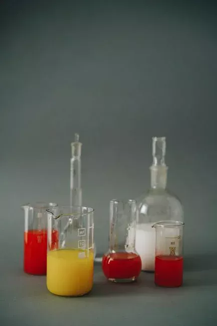
A DAF system requires chemical conditioning to be effective, as an aerated tank alone cannot remove suspended solids. Coagulant and polymer flocculant are dosed upstream of the flotation cell, and acids or bases are used to adjust pH to the window the coagulant requires (Clearwater, clearwaterind.com). For beverage streams, this window typically lands on the acidic side because fruit and soft-drink effluents arrive with low pH; jar testing on the actual stream is the only way to set the dose.
Two conditioning geometries are in common use. A flocculation tube — a serpentine pipe run with dosing ports for coagulant, pH adjustment, and polymer — provides a flash-mixing contact time of 15–45 seconds, which suits fast-reacting inorganic coagulants such as PAC or alum paired with a high-molecular-weight anionic polymer. Mix tanks with impeller agitators are used when extended contact time is needed, for example with emulsion-breaking chemistries on dairy or brewery CIP (Clearwater, clearwaterind.com). The number of tanks scales with the number of chemicals being introduced.
The conditioning skid is part of the DAF specification, not an optional extra. It typically ships as an automatic chemical dosing skid with a pH sensor, sample valves, and PLC-controlled dosing pumps. Better conditioning produces a thicker, more dewatered float, which lowers sludge volume sent to the downstream filter press and reduces polymer consumption in dewatering.
DAF Design Parameters a Beverage Plant Must Specify
Five parameters set the skid. None of them should be left to vendor defaults — each one should appear in the bid document with a number the supplier is committing to.
| Parameter | What it sets | Typical range / value | Source |
|---|---|---|---|
| Surface loading rate (m/h) | Tank area for a given flow | Set by vendor; require in writing | — |
| Hydraulic residence time (min) | Time the bubble column has to contact floc | Set by vendor; require in writing | — |
| Recycle ratio (% of clarified flow) | Air delivered per unit of treated water | Design trade-off; not a fixed number | — |
| Micro-bubble size (µm) | Float quality, air-saturation energy | 20–30 (regenerative turbine) or 30–50 (conventional) | PEWE (pewe-usa.com); Clearwater (clearwaterind.com) |
| Chemical dose (coagulant mg/L, polymer mg/L, pH) | Float formation and float solids | Determined by jar test on actual effluent — not generic | Clearwater (clearwaterind.com) |
The first two — surface loading and HRT — together set the tank footprint. Recycle ratio is a real design trade-off: more recycle delivers more bubbles per cubic metre of treated water and improves float formation, but consumes more pump energy and dilutes the clarified stream; the optimum is stream-specific. Micro-bubble size is a vendor choice: regenerative-turbine aeration delivers 20–30 micron bubbles without a compressor (PEWE ROGUE MAX RGT, pewe-usa.com), while conventional saturator-plus-compressor systems deliver 30–50 micron bubbles (Clearwater, clearwaterind.com). Smaller bubbles improve contact with fine colloids and produce a tighter float; they also demand tighter air-saturation control.
Chemical dose must come from a jar test on the actual beverage effluent, not from a generic dosing table. A HydropureWater DAF system from the manufacturer's 13-model range is offered for 4–300 m³/h across FOG, oil and grease, suspended solids, and colloidal-matter applications, per the verified product catalog (HydropureWater verified catalog).
From DAF Effluent to Reuse or Compliant Discharge
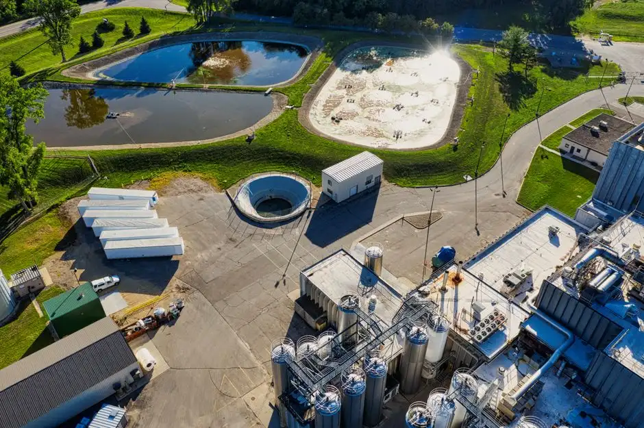
Two discharge paths are credible for a beverage plant. The first is discharge to a publicly owned treatment works (POTW) under a pretreatment permit; the DAF effluent must meet the local discharge limits and the POTW's local limits, which the buyer should obtain in writing before sizing the DAF. The second is on-site reuse, which routes the DAF underflow to an MBR membrane bioreactor for polish, with optional ultrafiltration or reverse osmosis downstream for higher-purity reuse streams such as CIP rinse or boiler feed.
The reuse path is real, not theoretical. A pilot study on food and beverage wastewater compared hollow-fiber and flat-sheet MBR configurations at mixed liquor suspended solids of 6,000 mg/L and 12,000 mg/L and reported COD and TSS rejection rates of more than 84% across both membrane types, with silt density index (SDI) of 1–2.38 — comfortably below the SDI 3 threshold that RO membranes require for feedwater (Membranes 2021, PMC8235490, doi:10.3390/membranes11060456). The SDI being inside the RO envelope is the signal that the DAF effluent is membrane-ready. The settled sludge from the DAF is sent to a plate and frame filter press for dewatering, which closes the solids mass balance on the line.
Selecting a DAF Skid: A 2026 Buyer Decision Framework
Translating the technical requirements into a procurement decision takes four steps. First, match the hydraulic envelope to the design flow: small-to-medium flows with very high contaminant load suit a low-profile cross-flow separator (Clearwater FPAC family), while large flows with medium-to-large loads suit a high-profile plate-style unit (FPBC for low-to-medium loads with low-buoyancy particles; FPHF for large flows with medium-to-large loads) (Clearwater, clearwaterind.com). Second, match the skid architecture to the flow rate: a turnkey compact DAF with chemical conditioning, instruments, and PLC is appropriate for flows of 66 GPM or less on a single skid, and a modular two-skid build is used for flows above 66 GPM (Clearwater, clearwaterind.com). Third, confirm the bubble-size technology — 20–30 micron regenerative-turbine aeration versus 30–50 micron conventional — in writing, because that choice drives air-saturation energy, float quality, and maintenance scope (PEWE, pewe-usa.com; Clearwater, clearwaterind.com). Fourth, demand a jar-test report on the actual beverage stream before signing the PO, because chemistry and surface loading are coupled and cannot be set from a generic table (Clearwater, clearwaterind.com).
Validate that the manufacturer's standard model range covers the plant's design flow: the HydropureWater DAF system range offers 13 standard models from 4 to 300 m³/h, sized for FOG, oil and grease, suspended solids, and colloidal-matter removal (HydropureWater verified catalog). For a fuller cost and spec framework, the 2026 best DAF unit decision framework walks through CAPEX line items, and the DAF maintenance cost in 2026 OPEX breakdown covers annual spend, with a supporting DAF troubleshooting guide for post-commissioning issues.
Frequently Asked Questions
What flow rate and contaminant load range should I size a DAF for in a beverage plant?
Size for the peak hourly flow that the CIP and product-changeover cycles actually produce, not the daily average, because the float blanket has to ride out the surges without dumping solids. The HydropureWater DAF range covers 4 to 300 m³/h across 13 standard models for FOG, oil and grease, suspended solids, and colloidal matter (HydropureWater verified catalog). Request the manufacturer's surface loading rate and hydraulic residence time figures in writing, matched to your peak flow, before signing the PO.
Does DAF remove enough on its own, or do I need an MBR or RO downstream?
For POTW discharge, a well-conditioned DAF is usually sufficient as a primary clarifier; confirm the local
Frequently Asked Questions
What is the typical DAF removal efficiency for FOG and TSS in beverage wastewater?
In well-optimized beverage wastewater applications, a Dissolved Air Flotation (DAF) system typically achieves FOG removal efficiencies ranging from 90% to 98% and Total Suspended Solids (TSS) removal between 85% and 95%. These figures assume proper chemical conditioning and a surface loading rate maintained between 1.5 and 3.0 gpm/ft².
How do I size a DAF system for a beverage plant with seasonal flow surges from CIP?
Sizing must be based on the peak hydraulic load during Clean-in-Place (CIP) cycles rather than average daily flow to prevent hydraulic washout of the float layer. Engineers should design for a peaking factor of 1.5x to 2.5x the average flow rate, utilizing an equalization tank with a minimum retention time of 8 to 12 hours to dampen the impact of high-temperature, high-pH slug loads.
Is a DAF alone enough to meet POTW discharge limits for beverage effluent, or do I need an MBR or RO downstream?
A DAF is typically classified as primary treatment and is generally sufficient if POTW limits focus on TSS, FOG, and pH. However, if discharge permits mandate strict BOD/COD limits below 250 mg/L or specific nutrient removal, a DAF alone is insufficient; downstream biological treatment such as an MBR or an anaerobic/aerobic reactor train is required to treat the dissolved organic fraction.
What chemical dosing — coagulant, pH, polymer — is required upstream of a DAF in a beverage plant?
Effective flocculation typically requires a pH adjustment to a range of 5.5 to 7.0 using sulfuric acid or sodium hydroxide, followed by the addition of metallic salts (such as ferric chloride or aluminum sulfate) at dosages of 50 to 200 mg/L. A high-molecular-weight anionic or cationic polymer is then injected at 1 to 5 mg/L to bridge micro-flocs into larger particles suitable for flotation.
How much does a DAF system for a beverage plant cost in 2026, and what drives the price?
As of 2026, a complete skid-mounted DAF system for a mid-sized beverage facility typically ranges from $150,000 to $450,000, excluding civil works and installation. Total project costs are driven primarily by the required hydraulic capacity, the choice of materials (304 vs. 316 stainless steel for corrosion resistance against CIP chemicals), and the complexity of the integrated control and chemical feed automation systems.