
Why Detergent Wastewater Challenges a Conventional DAF
Detergent manufacturing waste streams are not generic industrial wastewater. They carry anionic surfactants from the linear alkylbenzene sulfonate (LAS) family, nonionic alcohol ethoxylates, builders such as sodium tripolyphosphate and zeolite 4A, plus emulsified oils and fragrances — a colloidal population dominated by surfactant micelles rather than free oil droplets. Per the Wikipedia entry on dissolved air flotation, the unit operation is well established for industrial wastewater containing suspended matter, oil, and solids, so the technology itself is appropriate; the design problem is that surfactant chemistry changes the separation physics.
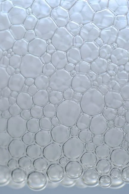
Micelles keep colloidal mass in stable suspension, and surfactant molecules lower surface tension, so air introduced into the saturator or float tank foams more aggressively than in a refinery or food duty. A detergent-duty DAF must include foam capture at the skimmer, a defined defoamer protocol, and a saturator vent strategy. The supplied research does not quote a default foam-control dose, so this must be confirmed in a jar test rather than copied from another industry.
Step 1: Characterize the Influent Before Sizing the Unit
No DAF design should be sized on assumed feed values. Before selecting a unit, the plant lab needs to return a parameter sheet covering average and peak flow (m³/h), peak factor, pH, temperature, total suspended solids (TSS), chemical oxygen demand (COD), biochemical oxygen demand (BOD), fats/oils/grease (FOG), anionic and nonionic surfactant concentration as mg/L LAS-equivalent, and calcium/magnesium hardness, because hardness ions interact with anionic surfactants and shift micelle behaviour. The downstream discharge or reuse limit on TSS, COD, and residual surfactant then defines the upstream removal target the DAF must hit. Flow range should be cross-checked against a vendor's standard model line — for reference, the HydropureWater DAF system (4–300 m³/h) covers 13 standard models and gives the engineer a sizing envelope to compare design flow plus recycle against.
| Parameter | Unit | Sample to take | Why it matters for DAF design |
|---|---|---|---|
| Flow (avg / peak) | m³/h | 24-hour composite + grab on shift change | Sets hydraulic loading and saturator recycle |
| pH | — | Online probe + grab | Defines coagulant working window |
| Temperature | °C | Inline | Changes air solubility in the saturator |
| TSS | mg/L | Composite | Drives A/S ratio and sludge yield |
| COD / BOD | mg/L | Composite | Defines downstream biological load |
| FOG | mg/L | Grab, refrigerated | Sets skimmer frequency |
| Anionic surfactant (as LAS) | mg/L | Grab, refrigerated | Sets coagulant demand and foam risk |
| Nonionic surfactant | mg/L | Grab, refrigerated | Affects micelle charge neutralization |
| Hardness (Ca/Mg) | mg/L as CaCO₃ | Grab | Interacts with anionic surfactant and builders |
| Discharge/reuse target | mg/L TSS, COD, surfactant | Permit document | Defines removal the DAF must deliver |
Step 2: Select Coagulation and Flocculation Chemistry
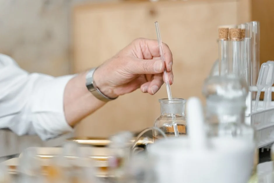
Per the Wikipedia DAF article, the feed to a float tank is often dosed with a coagulant such as ferric chloride or aluminum sulfate to destabilize colloids, and sometimes with a flocculant to build larger clusters. For detergent streams, the priority is neutralizing the negative charge on anionic surfactant micelles so bubbles can attach, which is why HydropureWater's automatic chemical dosing skid typically combines a metal coagulant (ferric chloride, aluminum sulfate, or polyaluminum chloride) with a cationic polymer. The polymer is the workhorse for anionic surfactant neutralization; the metal coagulant handles suspended solids and phosphorus builders. Because the supplied research does not provide a default dose for surfactant-bearing streams, the dose, pH window, and flocculant charge must be confirmed by jar test on the actual plant effluent. Operating pH matters: outside the working window of the chosen metal coagulant, residual metal carryover increases and floc quality collapses, which is the most common cause of a detergent-duty DAF underperforming its rated TSS removal. The jar test should bracket at least three coagulant doses, two flocculant doses, and a pH range of 6 to 9 so the engineer can see the dose-response surface before committing to a full-scale setpoint.
Step 3: Size the Saturator, Recycle Ratio, and Microbubble Population
Per Wikipedia, a portion of clarified effluent is pumped into a small pressure vessel called the air drum, where compressed air dissolves into the water; the air-saturated stream is then recycled through a pressure-reduction valve at the front of the float tank, releasing air as tiny bubbles that nucleate on suspended particles and lift them. Three numbers drive this air-side design: recycle ratio, saturator pressure, and microbubble size distribution. Recycle ratio sets the air-to-solids ratio (A/S) — the mass of air delivered per mass of solids to be floated — and is a jar- and pilot-test input. Saturation pressure sets dissolved-air concentration; the saturator and air compressor datasheet is the right place to read this from, since residence time, temperature, and packing all shift the equilibrium. Microbubble size is the lever for attachment efficiency on fine colloids and surfactant micelles: finer bubbles give more surface area per unit of air, which matters when the target is sub-100 µm floc. Request bubble-size distribution data (typically 10–100 µm range) from the DAF supplier and check it against the particle size of the destabilized floc from your jar test.
| Air-side parameter | What it controls | Where the value comes from |
|---|---|---|
| Recycle ratio (R/Q) | Air-to-solids ratio, bubble density in float tank | Jar test and pilot; supplier datasheet for envelope |
| Saturator pressure | Dissolved-air concentration at equilibrium | Air drum and compressor datasheet |
| Saturator residence time | Approach to saturation | Vendor design; check against feed temperature |
| Pressure-reduction valve setting | Bubble formation at float tank inlet | Vendor setpoint; matched to saturator pressure |
| Microbubble size distribution | Attachment efficiency on fine colloids and micelles | Supplier measurement; cross-check vs. floc size from jar test |
| Air-to-solids (A/S) ratio | Floating capacity per kg TSS fed | Jar test with variable recycle; pilot confirmation |
Step 4: Choose Tank Geometry and Hydraulic Loading
Per Wikipedia, circular DAF systems are more efficient and require only about 3 minutes of residence time, while rectangular DAF systems need 20 to 30 minutes; the spiral scoop used in circular units is a real advantage when footprint is constrained or foam must be removed cleanly from a small surface area. Some DAF designs add parallel-plate (lamella) packing inside the float tank to increase effective separation surface, which improves performance on the fine, low-density flocs typical of micelle-bearing streams. The hydraulic loading rate — surface overflow rate in m/h — must be checked against the supplier's rated value for the chosen geometry; this is one of the numbers an engineer should pin down during supplier selection rather than assume, because rectangular and lamella units have very different ratings. Proper geometry selection ensures a stable froth blanket, which improves skimming efficiency for foaming surfactant streams.
Step 5: Skimming, Foam Handling, and Sludge Routing
Per Wikipedia, the froth layer that forms on top of the float tank is skimmed off while clarified water exits from the bottom. On a detergent line, the skimmed sludge is high in surfactant, FOG, and solids, and the foam is also where excess surfactant and defoamer residue concentrate. Route the skim to a sludge dewatering stage — the HydropureWater plate and frame filter press handles this kind of surfactant-rich float — and not back to the head of the plant, or the DAF will see a second pass of material it has already floated. Foaming carryover from the saturator must be vented through a dedicated foam knock-out pot, and a silicone- or fatty-alcohol-based defoamer dosing line on the saturator vent is standard practice; the dose is site-specific and must be tuned during commissioning. Skimmer speed and blade depth are also worth specifying: a shallow blade set just above the water-froth interface removes more sludge and less water, which improves cake solids in the downstream dewatering stage.
Step 6: Integrate the DAF With Downstream Treatment
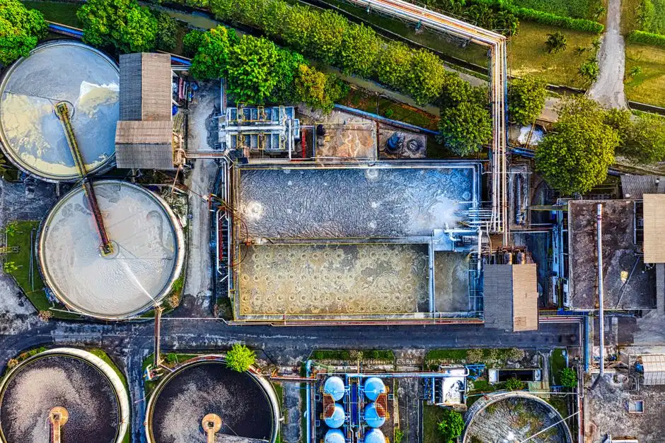
DAF is a primary or pre-treatment step, not a complete solution for detergent wastewater. A well-run DAF removes suspended solids, emulsified oil, and a fraction of the colloidal surfactant, but the soluble COD and the remaining soluble surfactant need a polishing step. For most discharge permits, conventional activated sludge is sufficient as long as the DAF has removed the FOG and foam-forming load that would otherwise upset the biology. For water-reuse targets, ultrafiltration downstream of the DAF produces a polish the DAF alone cannot reach; check the reuse specification before assuming UF is required. On a tight footprint, an MBR system (HydropureWater MBR system) combining activated sludge with submerged membranes can replace a separate clarifier and polishing step, and it tolerates the residual nonionic surfactant load better than a conventional clarifier. The TecnoLógicas review of DAF system parameters (revistas.itm.edu.co) documents the use of DAF combined with downstream biological stages across food, dairy, and industrial wastewater, providing a proven model for detergent plants.
Worked Example: Sizing a DAF for a 50 m³/h Detergent Line
Take a liquid-detergent formulation line discharging 50 m³/h average flow, pH 7–9, TSS around 800 mg/L, COD around 2,000 mg/L, and anionic surfactant (as LAS) around 200 mg/L. That flow is comfortably inside the HydropureWater DAF system (4–300 m³/h) envelope across 13 standard models, so a standard unit is feasible. Specify a circular DAF at roughly 3 minutes of residence (per Wikipedia) with lamella packing to add surface area for fine micelle flotation. Run a jar test bracketing three doses of ferric chloride or polyaluminum chloride plus a cationic polymer, at pH 6.5, 7.5, and 8.5, and read the floc size, settleability, and supernatant surfactant residual to set the full-scale dose. Assume a 20% recycle ratio and let the saturator and air-compressor datasheet set the pressure setpoint — request a bubble-size distribution curve with the quote. Route the skim to a plate and frame filter press for dewatering, and follow the DAF with an MBR for residual COD and surfactant. Compare this train against the best DAF unit for industrial wastewater in 2026 framework and the DAF vs sedimentation comparison before procurement signs off.
Frequently Asked Questions
What removal efficiency can a DAF realistically achieve on detergent wastewater?
The TecnoLógicas review of DAF system parameters documents high removal of suspended solids and FOG across industrial applications, but the supplied research does not quote a single efficiency figure for detergent wastewater that a buyer can use as a guarantee. Treat any vendor efficiency claim without a site jar test as marketing; request a pilot run on a slip-stream of the actual plant effluent before signing the purchase order.
Which coagulant works best for anionic surfactants in a DAF?
Cationic polymer or polyaluminum chloride (PAC) is the standard choice for neutralizing anionic surfactant micelles, with ferric chloride or aluminum sulfate handling suspended solids and phosphorus builders. The supplied research confirms the chemistry but does not give a default dose, so a jar test on the plant's own effluent is the only defensible way to set the dose; the dosing skid datasheet should list the dose range and pump turndown needed.
How much does a DAF system cost for a 50 m³/h detergent line, and what is the lead time?
The supplied research does not contain a price or delivery window, so these figures are project-specific. Ask each shortlisted vendor for a written quote that itemizes the DAF vessel