

Design Workflow Overview
A complete sanitary solvent weld sewer design progresses through six linked work stages: design flow estimation, pipe and fitting selection, hydraulic sizing, alignment and cover checks, jointing and installation QC, and the transition into downstream treatment. Designers first establish average daily flow, apply a peaking factor (commonly 2.5 to 4.0 per Ten States Standards for typical municipal collection), and add an infiltration and inflow allowance consistent with the project's sewer rehabilitation plan.
Pipe and fittings are selected as SDR35 PVC certified to ASTM D2729, CSA B182.1, or BNQ 3624-050, with the third-party certification documented for the jurisdiction. Hydraulic sizing uses Manning's equation with n = 0.009 for PVC, confirming that peak flow produces a velocity between 2 ft/s and 10 ft/s in the selected diameter. The alignment is checked for minimum cover, horizontal and vertical separation from water mains, and cleanout placement. Solvent cement per ASTM D2564 is specified with primer per ASTM F656 where the manufacturer requires it, and joint preparation and cure time are written into the contract documents. The collection system terminates at a headworks structure, a lift station wet well, or a gravity inlet to a treatment plant, with the invert elevation matched to the hydraulic grade line of the receiving unit. The steps below assume the engineer is laying out a new gravity collection system terminating at a packaged or membrane-based treatment works.
Hydraulic Sizing and Pipe Selection
Manning's equation for gravity flow in a full circular pipe is V = (1.486/n) × R^(2/3) × S^(1/2), where R is the hydraulic radius (D/4 for a full pipe), S is the slope, and n is the Manning roughness coefficient. For PVC solvent weld sewer pipe, IPEX specifies a Manning flow coefficient n = 0.009, the smoothest flow surface of any common piping material per the IPEX BDS product page (ipexna.com, 2025). The velocity target is 2 ft/s at peak flow to transport settleable solids, with 10 ft/s as the upper bound to prevent pipe erosion and hydrogen sulfide generation. SDR35 PVC provides adequate pipe stiffness for typical burial depths up to 20 ft where native soil and bedding meet ASTM D2321 requirements; deflection should still be checked against the long-term deflection limit of 5% for flexible pipe installations.
Fitting selection follows the IPEX BDS range: injection molded fittings from 3 to 8 in (75 to 200 mm) and fabricated SDR35 solvent weld fittings from 8 to 24 in (200 to 600 mm), all third-party certified to CSA B182.2 and BNQ 3624-130 and conforming to ASTM D2729 (ipexna.com, 2025). A 10% safety factor on the calculated diameter is appropriate where future growth or service area expansion is planned within the design horizon.
Minimum slopes for common diameters at 2 ft/s with n = 0.009, calculated from Manning's equation, are summarized below. These are the slopes a designer should treat as lower-bound values for the stated diameters at peak flow.
| Nominal Diameter (in) | Full-Pipe Flow at 2 ft/s (gpm) | Minimum Slope (ft/ft) |
|---|---|---|
| 4 | ~88 | 0.0033 |
| 6 | ~230 | 0.0019 |
| 8 | ~445 | 0.0013 |
| 10 | ~750 | 0.0010 |
| 12 | ~1,150 | 0.0008 |
For projects that approach the slope limits, a designer should verify the calculation against the local jurisdiction's criteria, which may impose a flatter minimum on larger diameters to control excavation depth. Where the calculated slope is steeper than 10 ft/s velocity, the diameter should be increased rather than the slope flattened to avoid solids deposition.
Solvent Weld Jointing Procedure and Quality Control
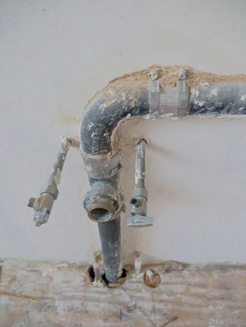
Solvent cement must meet ASTM D2564; primer, when used, must meet ASTM F656. For SDR35 sewer pipe, most manufacturers specify cement-only assembly on the spigot-and-socket joint, with primer reserved for schedule 40/80 pressure applications, so the project specification should call out the manufacturer-recommended procedure for the supplied pipe. The joint is made in five steps: cut the pipe square with a fine-tooth saw or wheel cutter; deburr the inside and outside of the cut; bevel the spigot end at 10 to 15° to chamfer the sharp edge; clean the socket and spigot with primer or the manufacturer's cleaner; and apply a uniform coat of cement to both surfaces before inserting the spigot fully into the socket with a quarter turn. The joint must be held in place for at least 30 seconds to prevent the pipe from backing out under spring-back load, and excess cement should be wiped from the exterior.
Cure time before handling is roughly 15 minutes at 60°F for a 4 in joint, with full cure taking 24 hours; colder ambient temperatures extend the cure time significantly, and heated cement or a warmer tented workspace is required below 40°F. The pressure test protocol commonly referenced is UNI-B-6, which allows either a 5 psi air test or a 10 ft water head test on a properly blocked section, with no pressure drop over 15 minutes accepted as pass. Common field failures trace to insufficient cement on the pipe, cold-weather installation without temperature-controlled cement, and contaminated socket or spigot surfaces from oil, mud, or standing water in the trench. Each of these is caught by a pre-construction mockup joint and a daily visual inspection of the first three assemblies of the day.
System Layout: Cleanouts, Manholes, and Connections
Cleanouts are placed at the upper terminal of every lateral, at 100 ft intervals on straight runs, and at every horizontal direction change greater than 45°. Manholes are required at every pipe size change, slope change, junction, and at a maximum spacing of 400 ft for inspection and rodding access. Minimum cover is 3 ft in non-traffic areas and 4 ft in traffic areas, with the deeper of the local frost depth or the traffic cover requirement used where the two diverge. Horizontal separation from potable water mains is 10 ft per Ten States Standards, with an 18 in vertical separation at crossings and the sewer pipe placed below the water main where clearance is limited.
Connections to existing mains are made with a saddle wye or a cut-in wye banded with stainless steel straps; solvent weld service connections should not be direct-tapped into a pressurized main. The transition from collection to treatment terminates at the headworks structure, a lift station wet well, or the inlet of a packaged treatment plant. The invert elevation at the receiving structure must match the hydraulic grade line of the collection system, and a drop manhole is used where the treatment inlet sits below the design slope of the incoming sewer.
Integration with Downstream Treatment Systems
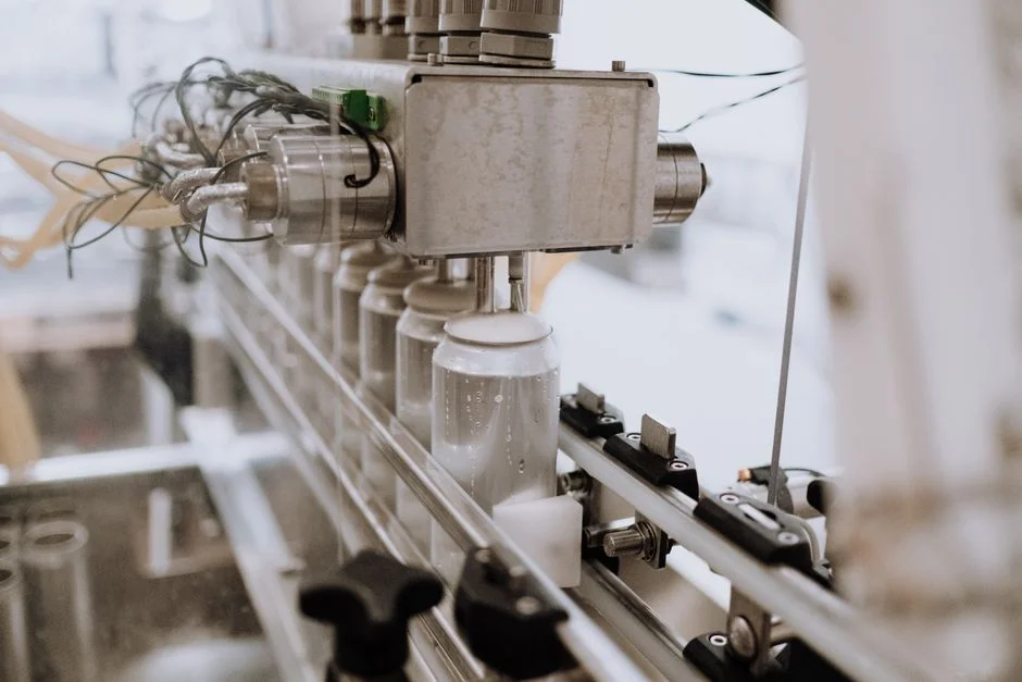
The downstream end of the collection system is the headworks of the treatment works, and the invert, screen opening size, and flow distribution at that interface determine how the upstream design performs in service. For a typical municipal or institutional project, the screened flow is handled by a rotary mechanical bar screen for headworks screening to remove rags, plastics, and fibrous debris before biological treatment. The screen inlet should be designed for peak hour flow rather than average daily flow, with a flow distribution weir or splitter box upstream to keep the approach velocity within the screen manufacturer's range. The screened flow is then routed to either an MBR membrane bioreactor for municipal sewage treatment sized for the 10 to 2,000 m³/day range for near-reuse effluent with sub-micron suspended solids, or to an underground package sewage treatment plant for 1 to 80 m³/h for smaller sites where footprint and burial depth are critical. Where diurnal variation is significant, equalization upstream of the MBR or membrane tank volume within the packaged plant is used to buffer the load. Solvent weld PVC is unaffected by sewer gases, sulfuric acid, and aggressive soil conditions per the IPEX BDS documentation (ipexna.com, 2025), which protects the upstream collection system while the downstream treatment handles BOD, TSS, and nutrient reduction. For project-level cost and compliance context that complements this design, see the municipal sewage treatment plant design guide for compliance and costs and the package wastewater treatment plant specifications and compliance guide.
Compliance Checklist and Documentation
Plan review and construction closeout depend on a consistent documentation package, and the items below are the minimum a reviewer will expect to see in the as-built submittal.
- Pipe and fittings certificates: ASTM D2729, CSA B182.1, CSA B182.2, BNQ 3624-050, BNQ 3624-130, with lot numbers recorded against the as-built alignment.
- Solvent cement: ASTM D2564 compliance with batch numbers; primer ASTM F656 if used; cold-weather installation log where ambient temperature drops below 40°F.
- Pressure test reports: UNI-B-6 air or water test logs with date, segment identification, test pressure, duration, and pass/fail for each tested section.
- As-built drawings: invert elevations, slopes, cleanout and manhole locations, pipe sizes, and connection details to lift stations or treatment works.
- Video inspection: post-construction CCTV per NASSCO PACP coding to establish a baseline condition for the owner's asset management file.
- Operation and maintenance manual: cleanout access, screening maintenance schedule, and treatment plant startup sequence tied to the commissioning plan.
For projects where water reuse or closed-loop industrial water is being considered downstream, the industrial water reduction strategies with closed-loop recycling guide outlines the additional treatment steps that would interface with the MBR or packaged plant covered above.
Frequently Asked Questions
What is the maximum burial depth for SDR35 PVC solvent weld pipe before deflection controls design?
SDR35 PVC is generally acceptable for burial depths up to roughly 20 ft where native soil and bedding meet ASTM D2321 requirements, but deflection rather than strength is usually the controlling limit. The designer should run a long-term deflection calculation against the 5% limit for flexible pipe and request the manufacturer's stiffness and deflection data for the specific product being supplied.
How do I size a solvent weld sewer lateral for a 50-bed hospital with peak flow of 150 gpm?
Apply Manning's equation with n = 0.009 at the 150 gpm peak, target a minimum velocity of 2 ft/s, and select a diameter and slope combination that meets the velocity criterion while keeping peak velocity below 10 ft/s. Confirm the selected slope against the local jurisdiction's minimum slope table, then add a 10% safety factor on diameter for future expansion before finalizing the callout.
Can solvent weld PVC connect directly to an MBR inlet screen without a manhole?
Direct connection without an access structure is not recommended because the screen, splitter box, and flow distribution weir all need periodic inspection and the upstream sewer still requires access for rodding and CCTV. A manhole or junction structure at the headworks interface is the standard detail and should be shown on the plan and profile sheets.
What solvent cement cure time is required at 40°F before pressure testing?
Cure time at 40°F is roughly double the 60°F value, so a 4 in joint that cures in 15 minutes at 60°F will need around 30 minutes before handling and the full 24-hour cure before pressure testing. The contractor should follow the cement manufacturer's published cure-time chart for the specific product, keep the cement and primer above 40°F before use, and record the ambient temperature at the time of each joint on the QC log.