Why CAF Systems Underperform: A Diagnostic Framework
Cavitation air flotation (CAF) treats industrial wastewater by forming a floc blanket inside a cavitation chamber within roughly 2–4 seconds, then floating that blanket into a downstream chamber held at about 17 minutes retention (S4, 1995). When performance drops, the failure traces to one of four design criteria: chemical program, air injection and floc flotation, flotation clarification, and solids/liquid separation (S4). Treating those four criteria as a triage order—chemistry first, cavitation aerator second, weir and retention time third, scraper and auger fourth—turns an underperformance issue into a manageable decision.
The 1995 source quantifies the cost of missing a CAF target: suspended solids typically carry 30–70% of influent BOD, so a 10-point SS slip cascades into biological loading, potentially failing the discharge permit or inflating the operating cost of the downstream biological stage (S4, 1995). CAF was designed to remove three failure modes common in DAF systems—blocked injection nozzles, the air-saturation ceiling, and the compressor/recirculation-pump energy load—by drawing ambient air through a draft tube at roughly 1 ft³/s instead of dissolving it under pressure (S4, 1995). Operators who default to "air supply problem" on a CAF often troubleshoot the wrong machine, and the four-stage framework provides the necessary corrective. For installation context, the step-by-step 2026 guide to cavitation air flotation installation and commissioning shows the same four criteria in startup order.
CAF Reference Parameters: The Numbers to Compare Against
The table below provides the parameter card for operator reference. Every number comes from the 1995 source (S4) or the SIGMADAF vendor reference (S3, 2025-12-01). The 10–15% drift rule at the end is a working heuristic a buyer should pressure-test against their own jar-test baseline before relying on it in an audit.
| Parameter | Design value | Source |
|---|---|---|
| Cavitation chamber floc retention | 2–4 s | S4, 1995 |
| Flotation chamber retention | ~17 min | S4, 1995 |
| Impeller speed | 1,700 rpm | S4, 1995 |
| Motor power (small unit / up to 20 m³/h) | 2.5 hp | S4, 1995 |
| Motor power (up to 150 m³/h) | 3.5 hp | S4, 1995 |
| Bubble size | 500 nm–1 mm | S4, 1995 |
| Natural recycle | 20–25% of hydraulic flow | S4, 1995 |
| Aerator air output | ~1 ft³/s (≈4× air DAF can dissolve) | S4, 1995 |
| Vendor flow range (SIGMADAF CAF) | 3–250 m³/h, AISI 304/316 | S3, 2025-12-01 |
| Vendor-reported SS / FOG removal | up to 95% SS, 99% FOG in pretreatment duty | S3, 2025-12-01 |
Check this first: Log the actual chamber retention, impeller rpm, and recycle ratio once per shift. Any parameter that has drifted more than 10–15% from the table above is the most likely root cause of the observed problem, before any chemistry re-dose is attempted.
Problem 1 — Floc Won't Form or Disperses in the Cavitation Chamber
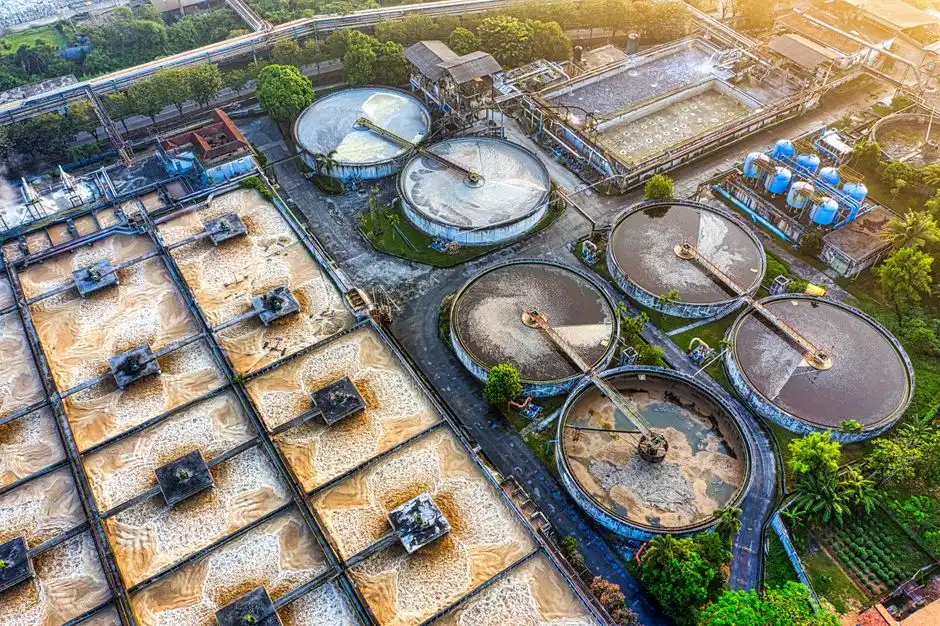
Milky effluent, no visible blanket on the chamber surface, and SS removal slipping from 90%+ toward single digits indicates that the 2–4 second cavitation-chamber window is not being utilized (S4, 1995). The floc must form immediately when the water enters the chamber, so any reaction-kinetics delay appears here first. The 1995 source specifies that the system requires a two-chemical program: an inorganic coagulant to neutralize electrostatic repulsion, followed by an organic flocculant to agglomerate destabilized particles into floes large enough for the microbubble blanket to lift (S4, 1995). Skipping the coagulant, inverting the order, or dosing both chemicals at the same injection point produces pin floc that drifts under the beach instead of rising.
The three checks to run in order are: (a) coagulant dose and contact time before the flocculant injection point; (b) flocculant dose and molecular weight against the current solids loading; (c) pH window for the chosen coagulant, as most inorganic coagulants collapse outside a narrow band. Standard 30-minute jar tests are often inappropriate here; reaction kinetics in a 2–4 s chamber require that the jar test be read against the in-line contact time. Check this first: Run a jar test whose shortest read time matches the 2–4 s chamber window; if SS removal does not recover, the failure is not chemistry—escalate to Problem 2. For a dosing skid that can be sequenced to the chamber residence, see the automatic coagulant and flocculant dosing skids.
Problem 2 — Microbubble Blanket Disappears or Air Draw Drops
Visible loss of fine bubbles in the chamber, whitewater turning clear, and a sudden drop in FOG removal point to the cavitation aerator. The 1995 source ties microbubble generation to the vacuum created by the hollow four-pronged impeller: ambient air is pulled down the draft tube at roughly 1 ft³/s to fill the void, and the cavitation/shear combination breaks that air into microbubbles between 500 nm and 1 mm (S4, 1995). If the vacuum collapses, the impeller stops pulling air, the recycle ratio drops below the 20–25% design band, and the blanket disappears regardless of chemical efficacy.
Four mechanical suspects are worth checking in this order: impeller vane erosion, draft-tube air-leak at the flange, motor V-belt slip, and seal failure on the geared drive. Check this first: With the inlet isolated, the chamber should hold a clear vacuum on a manometer; loss of vacuum under static conditions indicates a draft-tube air leak rather than a chemistry or flow problem. If the manometer holds, the impeller, belt, and seal are the next suspects.
Problem 3 — 'Sinkers' and Solids Carryover from the Flotation Chamber
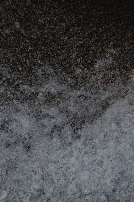
Dark specks passing under the beach and high turbidity on the clarified-weir discharge indicate a hydraulic-stability problem in the flotation chamber. The source specifies approximately 17 minutes of retention as the design optimum for both water clarification and surface-sludge thickening, and three factors disrupt this retention (S4, 1995). First, an influent flow surge that exceeds the natural 20–25% recycle ratio and short-circuits the chamber. Second, an adjustable weir set too low, causing the surface sludge blanket to be dragged under the beach. Third, a scraper speed set too high, which re-entrains the blanket before it can thicken.
The sequenced fix is: verify influent flow against the nameplate, raise the adjustable weir in small increments while observing the beach overflow, and slow the variable-speed scraper/auger drive. The 1995 source notes that "sinkers" are rarely a problem on a properly designed CAF because the air mass is sufficient to lift them; persistent sinkers suggest the chamber is being operated outside its design window (S4, 1995). Check this first: Do not increase aerator speed to push sinkers upward; the cavitation chamber is sized for floc formation, and over-aerating destroys floc. Adjust weir height and scraper speed instead of aerator rpm.
Problem 4 — Thick, Hard-to-Handle Float Sludge and Beach Buildup
Sludge piling on the beach, auger torque alarms, and water carryover are scraper/auger subsystem symptoms, but the 1995 source notes that surface-sludge thickness is controlled by scraper speed and weir height, both driven by a 1/2 hp geared motor with a variable-speed drive (S4, 1995). When the beach stops clearing, operators should check whether the auger current is climbing before the beach clears; this is the signature of a chemistry problem upstream. Over-dosing flocculant produces a dense, watery float that overloads the 1/2 hp auger, meaning the "sludge problem" is often a Problem 1 symptom in disguise.
The corrective is a torque-vs-speed log: if auger current climbs before the beach clears, reduce flocculant dose in 5–10% increments. The 1995 source notes that float sludge is often highly recyclable; pulp and paper installations report returning CAF float to the pulper and recovering costs in 3–6 months through fiber and heat-energy recovery (S4, 1995). Check this first: Confirm the float is being dewatered downstream rather than re-blended with the feed; a downstream plate and frame filter press for float-sludge dewatering will reduce auger load more reliably than any in-tank adjustment.
Preventive Maintenance Cadence and the Chemistry-vs-Mechanics Decision Rule

The following cadence provides a template for maintenance; buyers should tune these frequencies to their specific duty cycle. Daily: monitor influent flow, weir position, and beach appearance. Weekly: perform jar tests against the 2–4 s chamber contact time, and trend aerator/auger current on a single chart. Quarterly: check impeller vane thickness at the leading edge, draft-tube flange torque, and V-belt tension. Annual: replace gearbox oil and seals, and perform a full chamber inspection with the aerator removed.
The decision rule is critical for operators: if a jar test against the 2–4 s contact time restores ≥90% SS removal within 30 minutes, the problem is chemistry and the corrective is in the dosing skid. If the jar test does not restore removal, escalate to mechanical inspection of the cavitation aerator before changing chemical setpoints, as adding more coagulant to a chamber lacking microbubbles will not solve carryover and will complicate sludge handling. The source documents expected performance at 90%+ SS removal, with FOG removal of 96–97% in tannery and food-processing duty (S4, 1995). For plants standardizing on flotation pretreatment, the 2026 DAF retrofit and upgrade guide covers the parallel decision tree for DAF systems.
Frequently Asked Questions
What is the most common cause of a sudden SS-removal drop on a running CAF unit?
The most common cause is the coagulant/flocculant program, because the 2–4 s cavitation-chamber window exposes reaction-kinetics delays immediately (S4, 1995). The first check is a jar test timed against the 2–4 s contact time, not a standard 30-minute beaker test; if the jar test restores removal, the fix is in the dosing skid.
How do I decide between a chemistry re-tune and a mechanical refurbishment?
Run a jar test against the 2–4 s chamber contact time. If the jar test restores ≥90% SS removal, the problem is chemistry. If the jar test does not restore removal, escalate to mechanical inspection of the cavitation aerator (impeller, draft-tube flange, V-belt, seal) before changing chemical setpoints. A buyer evaluating supplier selection should request documented impeller vane-thickness measurements and draft-tubing material certificates.
How long should a properly designed CAF take to form a visible floc blanket after startup?
Floc formation is intended to occur almost instantaneously when water enters the cavitation chamber, which has a 2–4 s retention time (S4, 1995). The blanket should be visible at the chamber surface as soon as hydraulic flow is established. If the blanket does not appear within the first few minutes, the chemistry program is the primary suspect, followed by the cavitation aerator vacuum.
Is a CAF drop-in compatible with a plant that already runs a DAF?
Yes, though chemistry and hydraulic expectations differ. CAF was designed to overcome DAF failure modes—blocked injection nozzles, air-saturation ceilings, and high pump energy loads—by using a hollow four-pronged impeller and a draft tube (S4, 1995). A buyer