
What Screw Press Installation and Commissioning Actually Covers
Screw press installation and commissioning is a four-stage procedure: (1) site and foundation preparation with lifting access, (2) mechanical anchoring, leveling, and pipe/cable connection, (3) DRY commissioning — rotation direction, no-load motor amperage, and interlock verification at screw speeds below 1 rpm, and (4) WET commissioning — flocculant dosing tuning and acceptance against a target cake dryness of 18–25% DS and noise below 70 dB(A), benchmarked against a BS EN 15287-style acceptance protocol (BSI, 2026).
The vocabulary matters because EPC contracts split liability at the boundary between these stages. Installation is the civil, mechanical, and electrical handover that takes the unit from crate to energized but unloaded. Commissioning is the staged verification sequence that proves the unit is safe, then proves it does the job. A defensible Method Statement borrows the three-phase "design, install, commission" scaffolding from BS EN 15287 (the chimney standard, but the equipment lifecycle is identical) and overlays it with a DRY/WET split that protects people and equipment from a wiring or rotation fault before any sludge touches the machine (BSI, 2026).
For geometry, the reference unit is the HUBER Q-PRESS® multi-disc screw press: a slow-rotating auger operating below 1 rpm inside a cylindrical filter basket, with a pneumatically adjustable discharge cone that controls back-pressure and therefore cake dryness (HUBER, 2026). The same DRY/WET logic applies to a volute screw press — the filter basket, auger, and discharge geometry differ, but the acceptance targets and fault symptoms are essentially identical. Splitting commissioning into DRY and WET is not a paperwork convenience; it is the cheapest insurance against burning out a gearbox on a reversed phase or starving a flocculation reactor of polymer on day one.
Pre-Installation Site and Foundation Checklist
Most commissioning delays are not caused by the machine — they are caused by the site not being ready when the truck arrives. A pre-installation checklist signed off by the contractor and the client before delivery eliminates 70% of avoidable hold-points (HydropureWater field data, 2026).
| Item | Specification | Acceptance criterion |
|---|---|---|
| Foundation pad | Reinforced concrete, isolated from building structure | Flatness ≤2 mm/m; designed for wet operating weight + filtrate + sludge inventory |
| Floor drainage | Ventilated, dry room; floor drain at or below dewatering machine inlet | No filtrate pooling (per apoaqua preparation guidance, 2026) |
| Lifting access | Crane reach and door height verified against heaviest single lift | Rigging plan signed before delivery; handling team sized to weight and volume (apoaqua, 2026) |
| Power supply | Three-phase, voltage and IP rating per nameplate | Amperage headroom ≥25% above FLA; dedicated breaker |
| Process connections | Sludge feed, filtrate return, cake chute, polyelectrolyte dosing line | All stubbed and pressure-tested before the unit is set |
| Feed solids check | Feed DS measured at the upstream pump suction | Below 1% DS: pump feeding allowed without upstream thickener (HUBER, 2026) |
The feed-solids row is the one most often missed. If incoming sludge runs below 1% DS, a multi-disc or volute screw press can dewater it directly with pump feeding — no thickener, no extra CAPEX (HUBER, 2026). If the feed is consistently above this band and the upstream process cannot dilute it, the feed pump and pipe sizing need a pre-arrival review, because the screw press expects a low-pressure, high-volume feed rather than a thickened, high-solids feed.
Mechanical Installation: Anchoring, Leveling, and Alignment
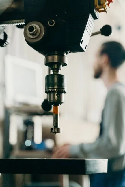
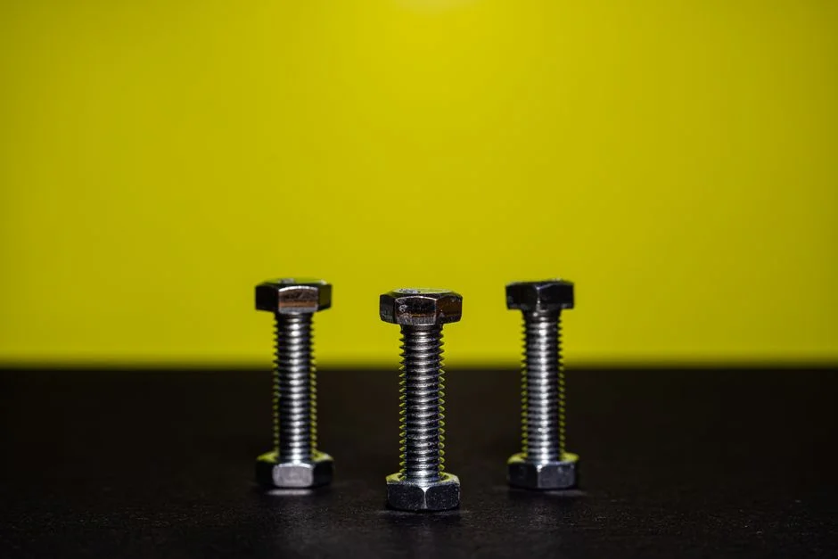
Mechanical installation is the single phase that, if rushed, generates the chronic vibration and premature bearing failure that operators later blame on "bad design." The order of operations is fixed: set on shims, level the unit, grout the baseplate, then re-torque the anchor bolts — anchor bolts alone are not a leveling device (apoaqua, 2026).
Once the baseplate is grouted, verify the axial alignment between the screw shaft drive and the gearbox coupling to ≤0.05 mm/m. Misalignment at this joint is the most common root cause of seal failure in the first six months of service (HydropureWater field data, 2026). Confirm that any counterweight block is firmly fixed and that the center of gravity sits over the base footprint; apoaqua explicitly flags counterweight security as a stability requirement (apoaqua, 2026). Re-torque the anchor bolts to specification after 24 hours of cure, and again after the first loaded run — grout creep under cyclic load will loosen any bolt that was not re-tensioned.
Piping, Cable, and Control Wiring
This section closes out the installation phase and brings the unit to "ready to energize" — the gate before DRY commissioning starts. Connect inlet, outlet, and filtrate piping at the specified diameter, and positively confirm the joint orientation before any valve is opened (apoaqua, 2026). Connect the power cable and confirm phase sequence at the motor terminal box; the very first DRY check is rotation direction, and a reversed phase silently rotates a pump or screw in the wrong direction with no alarm until something trips or breaks.
Wire the five primary control loops the Q-PRESS® exposes: sludge feed rate, flocculant dosing and mixing, screw shaft speed, sludge feed pressure, and the pneumatic counter-pressure on the discharge cone (HUBER, 2026). For sizes 620.2 and above, the segmented filter basket actuators and the backwash spray bar solenoid valves must also be wired and addressed on the PLC — the dewatering process is meant to continue uninterrupted during backwash on these sizes, so the control logic is part of the wiring scope, not an option (HUBER, 2026). Confirm the automatic polymer dosing system handshake signal is in the PLC, since flocculant tuning is the single largest variable in the WET phase.
Dry Commissioning: No-Load Safety and Integrity Checks

DRY commissioning is the most-overlooked section in competitor content, and it is the section that prevents the most expensive mistakes. No sludge enters the machine during DRY; the goal is to prove the unit is electrically and mechanically sound before anything biological does.
- Rotation direction. Jog the screw and confirm auger rotation matches the arrow on the housing. A phase swap is the number-one start-up fault — apoaqua lists "check whether the device is rotating in the correct direction" as the very first diagnostic step (apoaqua, 2026).
- No-load motor amperage. Record the baseline current at the nameplate VFD setting. A reading above nameplate FLA points to bearing drag or coupling misalignment; a reading well below expected points to a phase loss or a wiring error.
- Speed verification. Confirm the VFD ramp holds screw speed below 1 rpm throughout the no-load run (HUBER, 2026). Overspeed at this stage damages the screw flights before any process stress has been applied.
- Interlocks and E-stops. Prove every guard interlock, the discharge-cone overpressure trip, the backwash pump interlock, and the emergency stops before moving to WET. Log each test on the DRY commissioning sheet.
- Acoustic baseline. With the room otherwise quiet, the screw press should read below 70 dB(A) at 1 m (HUBER, 2026). Anything above that figure at no-load is a bearing or alignment problem, not a process problem.
If any of these five checks fails, fix it and re-run the DRY sheet. WET commissioning does not start until the DRY sheet is signed.
Wet Commissioning: Flocculant Tuning and Performance Acceptance
WET commissioning is the contractual moment of the whole exercise — the machine now runs on real sludge and the figures written into the acceptance certificate come from this run. Start the flocculation reactor and the sludge feed pump together, and ramp the feed rate to the design point over at least 15 minutes to avoid hydraulic shock to the basket (HydropureWater field data, 2026).
| Parameter | Setpoint / range | Tuning lever |
|---|---|---|
| Cake dryness (DS) | 18–25% | Pneumatic counter-pressure on discharge cone (HUBER, 2026) |
| Filtrate clarity | Visually clear, < ~500 mg/L TSS typical | Polymer dose, flocculant mixing intensity, backwash cycle |
| Polymer dose | Site-specific (typically 5–15 kg/t DS for municipal) | Watch cake discharge and filtrate — under-dose clouds filtrate, over-dose sticks the cone |
| Screw speed | < 1 rpm | VFD ramp; raise slightly to improve throughput, lower to raise DS |
| Backwash | Cyclic, segment-by-segment for sizes 620.2+ | Verify pressure pulsation on the filtrate return line, not just the spray bar (HUBER, 2026) |
Run the unit for at least 4 continuous hours at design load before capturing the acceptance figures. Sample cake DS by the oven-dry method (or the agreed online TSS probe), record throughput, polymer consumption in kg/t DS, specific energy in kWh/t DS, and noise at 1 m. If the cake sits below 18% DS, the usual suspect is polymer dose, then discharge cone counter-pressure, then feed rate — the sludge dewatering cake dryness troubleshooting guide walks the full diagnostic tree.
Performance Acceptance Parameters and Energy Benchmark
The acceptance table is what the owner signs against and what procurement uses to compare a screw press to a centrifuge. The figures below are the ones to copy into a purchase spec or a Performance Test protocol.
| Parameter | Acceptance target | Notes |
|---|---|---|
| Cake dryness (DS) | 18–25% | Multi-disc / volute screw press typical band (HUBER, 2026) |
| Sludge volume reduction | Up to 97% in a single step | Single-step, no upstream thickener required (HUBER, 2026) |
| Noise at 1 m | < 70 dB(A) | No acoustic enclosure required (HUBER, 2026) |
| Screw speed | < 1 rpm | Low-wear, low-noise operating regime (HUBER, 2026) |
| Energy vs centrifuge | 60–80% lower energy cost | Direct operating-cost comparator (HUBER, 2026) |
| Start-up / shut-down | Fully automatable, unattended; no filtrate loss | Centrifuges drop performance during ramp — screw press does not (HUBER, 2026) |
Convert the manufacturer's centrifuge kWh/t DS figure into the screw press equivalent (typically 0.2–0.5 kWh/t DS for a multi-disc press) and put both numbers on the same slide for the client. Capture as-built drawings, the I/O list, the PLC program with revision mark, the signed DRY and WET commissioning sheets, and the four-hour acceptance run data into the O&M handover file. If the client is also evaluating dewatering technologies side by side, the sludge dewatering energy and OPEX comparison puts the screw press against thickeners and centrifuges on the same axes.
Commissioning Troubleshooting Matrix
The matrix below replaces the thin "if it doesn't work, check the power" content on most vendor pages. Use it on-shift.
| Symptom | Likely root cause | Corrective action |
|---|---|---|
| Machine does not start | No power, loose cable, reversed phase | Check power, cable connections, and rotation direction first (apoaqua, 2026); only then check motor and controller |
| Unplanned stop during run | Sludge line blockage; feed pump fault | Inspect the sludge line; confirm the feed pump starts normally; check for broken pipes or leakage (apoaqua, 2026) |
| Power loss or fuse trip during run | Control board overheating; breaker / fuse rating mismatch; supply quality | Inspect main electrical control board for heat dissipation; verify breaker and fuse ratings match design; check supply (apoaqua, 2026) |
| Cake DS below 18% target | Polymer under-dose, then cone pressure, then feed rate | Step polymer dose first, then raise pneumatic counter-pressure on discharge cone; refer to the sludge dewatering cake dryness troubleshooting guide for the full tree |
| Filtrate turbidity rising | Clogged basket segments; spray bar solenoid fault | Inspect backwash cycle; verify segment actuators and spray bar solenoid valve operation; check filtrate return line for pressure pulsation (HUBER, 2026) |
Two non-obvious points from the matrix: a rising filtrate turbidity is almost always a backwash problem, not a polymer problem; and a fuse trip is a heat-dissipation or rating problem before it is a supply problem. Both are caught in DRY commissioning if the sheet is actually filled in.
Frequently Asked Questions
How long does screw press installation and commissioning take on site?
Typically 3–5 working days for a single unit: 1 day for mechanical installation and electrical hookup, 1 day for DRY commissioning, and 2–3 days for WET commissioning and the 4-hour acceptance run. Add 1–2 days if the upstream thickener or polymer make-up unit is also being commissioned in the same window (HydropureWater field data, 2026).
What cake dryness should I write into the acceptance certificate?
18–25% DS is the typical multi-disc screw press performance band on municipal digested or waste-activated sludge (HUBER, 2026). Tighten the lower bound to whatever your disposal contract or haul-off tariff requires, and put a hold point in the contract that the unit must hit the lower bound across the full 4-hour acceptance run, not just on a single grab sample.
Does a screw press need prior sludge thickening?
Not necessarily. Pump feeding allows direct dewatering of thin sludges below 1% DS without a thickener, which removes both the CAPEX of a thickener and the OPEX of its polymer and power (HUBER, 2026). If the upstream process already delivers a thickened feed, the screw press still works — the operator just has less margin on the feed pump.
Can a screw press be commissioned for unattended automatic operation?
Yes. Process parameters — filtration pressure, screw speed, and drive load — are permanently monitored and the control loop keeps the unit in its optimum band, so the press can run timer-based or 24/7 unattended once the DRY and WET sheets are signed (HUBER, 2026). The handover file should still include the alarm dead-band table the operator will tune in the first month.
How does a screw press compare to a centrifuge on commissioning risk?
Lower. There is no high-speed rotating assembly to balance, no acoustic enclosure required (under 70 dB(A) at 1 m), and no decanter scroll wear to trend during ramp-up (HUBER, 2026). Energy use is typically 60–80% lower than an equivalent centrifuge, which also reduces the electrical hookup scope at installation (HUBER, 2026).
Related Equipment
- plate and frame filter press — specifications, capacity range, and technical data