
Why Lamella Clarifier Energy Use Matters in 2026
A lamella clarifier typically operates at a baseline energy intensity of 0.01–0.02 kWh/m³ of treated water (ScienceDirect, 2024 overview). For a 200 m³/h industrial plant running 24/7, this equates to an annual consumption of 17,500–35,000 kWh. At a representative U.S. industrial tariff of $0.11/kWh, this generates an annual operating cost of $1,925–$3,850; in EU markets with rates reaching $0.28/kWh, those costs escalate to $4,900–$9,800 per unit. Lamella systems are inherently more efficient than circular scraper clarifiers, which often consume 0.05–0.10 kWh/m³, yet the 2026 regulatory environment demands further optimization. Compliance frameworks such as ISO 50001:2018 require granular energy reviews, while SEC Scope-2 reporting and EU CSRD directives force facilities to justify the carbon footprint of individual sub-systems. For a 50 m³/h site, annual consumption is 4,380–8,760 kWh; for a 500 m³/h site, it climbs to 43,800–87,600 kWh. Reducing this energy footprint is a prerequisite for corporate sustainability reporting. Lower energy intensity also reduces Scope-2 greenhouse gas emissions by approximately 0.4–0.8 kg CO₂e per cubic meter treated in coal-heavy grids, which can translate into carbon credit eligibility under voluntary markets. Auditors conducting ISO 50001 re-certification in 2026 are specifically trained to look for sub-metered clarifier loads, so plants that fail to document them risk non-conformities during surveillance audits. Investors evaluating ESG performance increasingly benchmark water-treatment sub-systems, meaning small efficiency improvements can influence the outcome of green-bond financing rounds. For detailed design parameters that influence these baseline figures, refer to our lamella clarifier engineering specifications guide.
Where the Energy Actually Goes: A Lamella Clarifier Energy Mass Balance
Energy consumption in a lamella unit is concentrated in fluid transport and hydraulic management rather than mechanical agitation. Feed and transfer pumps typically account for 50–65% of total consumption, as they must overcome the hydraulic head required to push water through distribution channels and across inclined plates. Sludge recirculation pumps contribute 15–25%, while chemical mixing for flocculant preparation accounts for 5–10%. Because lamella units often utilize static inclined plates rather than mechanical floor scrapers, the energy penalty for scraping is frequently zero, distinguishing them from conventional circular clarifiers. Many operators lack sub-metering on these specific circuits, leading to an "energy gap" where losses are masked by larger plant-wide loads. A practical way to close this gap is to install dedicated kWh transducers on each pump motor starter panel; even clamp-on CT-based meters with logging capability reveal which circuit dominates the night-time base load. Operators frequently discover that the feed pump operates for 18–22 hours per day at partial load, an operating regime where throttling valves waste 20–30% of the input power that could otherwise be recovered through variable-speed control. Sludge pumps often run intermittently for short bursts; capturing these runtimes with a simple event logger helps justify smart-blowdown retrofits by quantifying wasted idle time. The remaining 2–5% consumed by controls and instrumentation is small in absolute terms but necessary for enabling efficiency measures, as PLCs, turbidity probes, and level transmitters must be reliable for advanced control strategies. To understand the fundamental differences in mechanical power requirements between these systems, consult our lamella clarifier vs alternatives comparison.
| System Component | % of Energy Allocation | Primary Energy Driver |
|---|---|---|
| Feed/Transfer Pump | 50–65% | Hydraulic head and pipe friction |
| Sludge Recirculation Pump | 15–25% | Sludge density and pipe head loss |
| Chemical/Polymer Mixer | 5–10% | Mixing intensity (G-value) |
| Controls and Instrumentation | 2–5% | PLC processing and sensor power |
| Mechanical Scraper | 0–15% | Motor torque (only if present) |
Six Engineering Levers to Cut Lamella Clarifier Energy Consumption
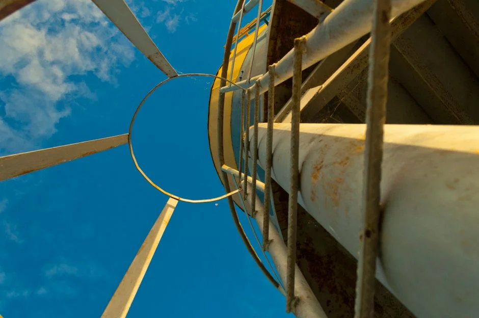
Optimizing a HydropureWater high-efficiency sedimentation tank (lamella clarifier) involves adjusting the hydraulic profile and control logic to minimize wasted work. Plate geometry tuning—raising the plate angle from 45° to 55–60° and tightening plate spacing from 100 mm to 50–80 mm—reduces the pumping head requirement by 10–20% while maintaining a surface loading rate of 20–40 m/h. Returning 10–20% of thickened sludge to the flocculation zone stabilizes the floc blanket, which reduces pump cycling by 15–25%. Installing a VFD on the feed pump allows the flow to match real-time demand, yielding 25–40% pump energy savings with a payback of 6–18 months. Integrating an automatic coagulant and polymer dosing system reduces chemical consumption by up to 30%, which shortens settling times and reduces the hydraulic load on pumps. Implementing smart sludge blowdown—using turbidity-based sensors rather than continuous timers—can cut sludge pump runtime by 30–60%. Finally, upstream flow equalization smooths diurnal peaks, allowing the feed pump to operate at a steady 70–85% of peak capacity, eliminating the energy penalty associated with oversizing equipment for transient spikes. Operators should sequence these levers: VFD installation and polymer optimization can be completed without process interruption, while plate re-spacing typically requires the basin to be drained. Flow-equalization tanks deliver compounding benefits by allowing downstream pumps to be specified closer to average flow rather than peak flow, reducing both installed motor size and standby pump count. Each lever should be validated with at least two weeks of post-retrofit sub-metered data, as interactions—such as reduced polymer dose combined with lower flow—can produce non-linear settling improvements. Combining these six levers can reduce the net energy footprint by 40–70%.
| Engineering Lever | Typical kWh/m³ Saved | Implementation |
|---|---|---|
| VFD Feed Pump Control | 0.005–0.008 | Retrofit/New |
| Smart Sludge Blowdown | 0.002–0.004 | Retrofit |
| Polymer Optimization | 0.001–0.003 | Process adjustment |
| Flow Equalization | 0.003–0.005 | System design |
| Plate Geometry Tuning | 0.002–0.004 | Major retrofit |
| Sludge Recirculation | 0.002–0.003 | Design/Retrofit |
2026 ROI Comparison: Payback by Lever
For a 200 m³/h plant, prioritizing low-capex, high-impact interventions is essential for meeting annual energy reduction targets. The combination of a VFD on the feed pump and smart sludge blowdown represents the most effective starting point, delivering roughly 35% total reduction with a payback period under 18 months. While hydraulic retrofits like plate spacing changes offer significant gains, they are best scheduled during major plant maintenance shutdowns. Operators should also factor in avoided demand charges, which in many deregulated U.S. markets add 8–12% to the savings realized by VFDs that limit peak kVA draw. Polymer optimization delivers the fastest cash return because chemical savings appear on the first invoice, though the energy component is modest and depends on whether dose reduction shortens settling time. Flow equalization and plate re-spacing remain attractive for greenfield or major expansion projects where civil works are already mobilized. A common 2026 sequencing approach is to deploy low-risk retrofits in year one, reserve hydraulic changes for the next planned turnaround, and revisit the model annually as tariffs and load profiles evolve. For sites looking to integrate multiple technologies, our data on anaerobic digester energy reduction strategies provides a blueprint for how integrated systems can further shift the facility-wide energy curve.
| Lever | Capex Band | Payback (Months) | Risk |
|---|---|---|---|
| VFD Feed Pump | Medium ($5k–25k) | 6–18 | Low |
| Smart Blowdown | Low (<$5k) | 6–12 | Low |
| Polymer Optimization | Low (<$5k) | 3–9 | Low |
| Flow Equalization | High ($25k+) | 18–24 | Medium |
| Plate Re-spacing | High ($25k+) | 24+ | High |
5-Step Energy Audit Checklist for an Existing Lamella Clarifier
- Sub-meter the feed pump and sludge pump circuits for seven consecutive days to establish a baseline kWh/m³ profile.
- Analyze influent flow variability over the 7-day period to determine the potential capacity for upstream flow equalization.
- Conduct a physical inspection of plate spacing and angle; compare against original design specifications to identify pumping head penalties.
- Evaluate current polymer dose and floc quality; track residual coagulant in the effluent to ensure dosing is not excessive.
- Model the projected kWh/m³ for each lever identified in this guide and build a 90-day implementation plan, starting with the VFD installation.
Frequently Asked Questions
What is the typical energy intensity of a well-operated lamella clarifier?
A well-optimized lamella clarifier operates in the range of 0.01–0.02 kWh/m³ of treated water. This figure can be reduced by 40–70% through the implementation of VFDs, smart blowdown controls, and optimized chemical dosing.
Why does the feed pump consume the majority of the clarifier's energy?
The feed pump accounts for 50–65% of the energy consumption because it must overcome the hydraulic head required to distribute flow evenly across the inclined plates. Reducing system head loss through plate geometry tuning or flow equalization directly lowers this demand.
How does sludge recirculation reduce energy consumption?
Recirculating 10–20% of thickened sludge stabilizes the floc blanket within the lamella system. This leads to improved settling efficiency, which reduces the frequency of sludge pump cycling and lowers the overall demand for chemical coagulants.
Related Equipment
- HydropureWater high-efficiency sedimentation tank (lamella clarifier) — specifications, capacity range, and technical data
- automatic coagulant and polymer dosing system — specifications, capacity range, and technical data