What an MBBR actually does — and why design turns on the carrier, not the bacteria
An MBBR (Moving Bed Biofilm Reactor) treats wastewater by growing biofilm on free-floating HDPE carriers (typically 20–70% tank fill) inside an aerated basin. Aerobic MBBRs routinely achieve 85–95% BOD and COD removal with effluent BOD/COD under 30 mg/L, while anaerobic MBBRs handle 1–5 kg COD/m³·d on high-strength industrial streams. Sizing is driven by applied surface area loading, commonly 30–50 g BOD/m²·day, not by MLSS.
Three carrier specifications govern every calculation in this guide. First, protected specific surface area — typically 500 m²/m³ for Kaldnes K1 — is the area actually available for biofilm colonization, after subtracting the fraction shielded inside the carrier's cross structure. Second, bulk density must sit close to 0.95 g/cm³ so the carrier fluidizes at modest aeration rates (SOTE 25–35%) without floating or sinking. Third, shape (K1, K3, K5, Biochip) determines both protected area and minimum slot aperture for the retention screen.
The shift in mental model matters: activated sludge is MLSS-limited, so the designer chases F/M and SRT. An MBBR is surface-area-limited — the engineer specifies the protected area required to metabolize a given BOD load, then derives everything else (tank volume, aeration, screen aperture) from that single number.
The four MBBR process regimes and their design envelope
Before any sizing number, the engineer must pick the right regime. Each carries a different OLR envelope, a different fill fraction, and a different downstream obligation.
Aerobic MBBR is the workhorse. Applied organic loading typically runs 30–50 g BOD/m²·day on the carrier's protected surface area, with carrier fill 30–70% by volume. Aerobic MBBRs handle BOD 200–1500 mg/L reliably and produce effluent BOD/COD below 30 mg/L when paired with a downstream clarifier, DAF, or MBR.
Anaerobic MBBR addresses high-strength industrial streams at 1–5 kg COD/m³·d volumetric loading. Pairing anaerobic and aerobic MBBRs in series is documented for simultaneous biogas production and polishing in municipal pilots (HydropureWater engineering guide, 2026).
Anoxic MBBR handles denitrification. The constraint is stoichiometric: a BOD:NO₃-N ratio above ~4:1 is needed for heterotrophic denitrification, otherwise methanol or acetate dosing is required. A comammox-dominated continuous-flow MBBR configuration cut N₂O emissions 46.1% (≈0.06% of incoming N vs ≈0.1% for a comparable SBR) by eliminating the non-aerated settling and decanting phases that drive SBR emissions (Bioresour Technol, 2025).
IFAS (Integrated Fixed-film Activated Sludge) is the most common MBBR specification in practice: carriers are added to an existing CAS basin to raise capacity without new civil works. Fill fraction is tuned to the new capacity target, typically 20–40%, so mixed liquor and biofilm coexist.
| Regime | OLR / Loading envelope | Typical fill fraction | Primary use |
|---|---|---|---|
| Aerobic MBBR | 30–50 g BOD/m²·day | 30–70% | BOD/COD removal, nitrification |
| Anoxic MBBR | 0.3–0.6 g NO₃-N/m²·day | 30–50% | Denitrification (carbon often dosed) |
| Anaerobic MBBR | 1–5 kg COD/m³·day | 30–60% | High-strength industrial + biogas |
| IFAS (in CAS) | Per aerobic OLR + MLSS | 20–40% | Retrofit capacity upgrade |
Carrier selection: surface area, density, and the Kaldnes benchmark
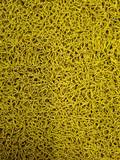
Kaldnes K1 is the reference carrier in this guide because it is the most documented. Its protected specific surface area sits in the 500 m²/m³ class, and its bulk density of approximately 0.95 g/cm³ lets it fluidize at coarse-bubble aeration rates of 15–25 m³ air per m² tank area per hour without washout.
A documented K1 pilot on laundry wastewater (Universitas Tanjungpura, 2019) ran at 20% fill fraction, 15-day biofilm seeding, and 10-day HRT, with air-injection aeration. Effluent results: COD dropped from 910 mg/L to 56.3 mg/L (93.81% removal), BOD from 441 mg/L to 39.67 mg/L (91% removal), phosphate from 38.24 mg/L to 5.31 mg/L (86.10%), and surfactant from 47.8 mg/L to 5.62 mg/L (88.22% removal). That pilot anchors the design assumption that a 20% fill K1 reactor at 10-day HRT lands inside the 85–95% BOD/COD band used in the opening paragraph.
Higher-area carriers (K3, K5, Biochip) raise the applied OLR ceiling by offering more protected area per cubic meter of media, but they tighten the downstream screening specification. The smallest carrier dimension shrinks as protected area rises, so slot aperture must follow it down — a 5–10 mm slot is typical for K1, and tighter screens are needed for K3 and K5. The selection rule: match carrier protected area to design OLR. Undersizing protected area is the single most common cause of poor MBBR performance in the field.
Step-by-step MBBR sizing calculation (worked example)
The worked example below takes a process engineer from raw influent numbers to a datasheet-ready parameter set. Inputs: Q = 500 m³/d, BODin = 800 mg/L, BODout ≤ 30 mg/L (96% removal), T = 25 °C, Kaldnes K1 with protected specific surface area of 500 m²/m³.
- BOD load to remove. 500 m³/d × 0.800 kg/m³ = 400 kg BOD/d to be metabolized.
- Required protected surface area. Use 15 g BOD/m²·d (conservative end of the 30–50 g BOD/m²·d range, leaving headroom for industrial variability). 400,000 g/d ÷ 15 g/m²·d = 26,667 m² of protected area.
- Media volume. 26,667 m² ÷ 500 m²/m³ = 53.3 m³ of K1 carriers.
- Tank volume at 40% fill. 53.3 m³ ÷ 0.40 = 133 m³.
- HRT check. 133 m³ ÷ (500 m³/24 h) = 6.4 h — inside the typical 4–8 h aerobic MBBR range.
- Aeration. Apply 1.5–2.0 kg O₂/kg BOD removed; for 400 kg BOD/d that is 600–800 kg O₂/d, or roughly 25–33 kg O₂/h. Size blowers and fine-bubble diffusers with a 1.5–2.0× alpha-corrected SOTE factor to convert clean-water SOTE (~25–35%) to field oxygen transfer (alpha ≈ 0.5–0.7 in mixed industrial liquor).
- Carrier retention screens. Perforated plate or wedge-wire with aperture smaller than the smallest carrier dimension. For K1, specify 5–10 mm slot on the effluent face to retain carriers; upstream headworks screening prevents debris from blinding these screens.
- Downstream separation. MBBR effluent carries suspended solids that the biofilm shears off. A secondary clarifier, DAF, or MBR is mandatory downstream — an MBBR does not separate solids on its own.
| Parameter | Symbol | Value | Notes |
|---|---|---|---|
| Flow | Q | 500 m³/d | Design average daily flow |
| Influent BOD | BODin | 800 mg/L | Mid-strength industrial |
| Target BODout | BODout | ≤30 mg/L | 96% removal |
| Design BOD loading | OLRdesign | 15 g BOD/m²·d | Conservative end of 30–50 band |
| Required protected area | Aprot | 26,667 m² | Step 2 |
| Media volume (K1, 500 m²/m³) | Vmedia | 53.3 m³ | Step 3 |
| Fill fraction | f | 40% | Aerobic design point |
| Tank volume | Vtank | 133 m³ | Step 4 |
| HRT | HRT | 6.4 h | Step 5 check |
| Aeration | O₂ demand | 600–800 kg O₂/d | 1.5–2.0 kg O₂/kg BOD |
| Screen aperture (K1) | slot | 5–10 mm | Wedge-wire or perforated plate |
When MBBR is the wrong choice — MBBR vs IFAS vs MBR
Decision rules for technology selection on a single datasheet:
- Specify MBBR for steady, mid-strength industrial loads (BOD 200–1500 mg/L) where nutrient removal and small footprint matter but reuse-quality effluent is not required. Effluent BOD/COD lands below 30 mg/L, but TSS still needs downstream separation.
- Specify IFAS when an existing CAS basin needs a capacity upgrade without new civil works — carriers are added to the aeration basin, and the suspended-growth biomass is retained. This is the most common MBBR specification in retrofit practice.
- Specify MBR (membrane bioreactor) when reuse-quality effluent is mandatory. MBR replaces the secondary clarifier with microfiltration or ultrafiltration membranes and physically filters out bacteria and suspended solids. For chemicals and high-strength streams, the trade-off is laid out in a side-by-side comparison of MBR vs conventional activated sludge for chemicals wastewater.
- Specify anaerobic + aerobic MBBR trains when high-strength industrial wastewater and biogas recovery are both on the table; anaerobic MBBR handles 1–5 kg COD/m³·d, aerobic MBBR polishes the effluent.
Two operational risks the datasheet must call out: media clogging and screen blinding if upstream headworks screening is inadequate, and dependence on a downstream solids-separation step. A rotary mechanical bar screen for MBBR headworks addresses the first risk; pairing the MBBR with an MBR membrane bioreactor for the downstream separation step addresses the second.
Real-world validation: two recent MBBR case studies
Two recent pilots land inside the performance band the worked example assumes, and both are citable on a datasheet.
Case 1 — Laundry wastewater, Kaldnes K1, 20% fill, 10-day HRT. The Universitas Tanjungpura pilot (2019) reduced BOD 91% (441 → 39.67 mg/L), COD 93.81% (910 → 56.3 mg/L), phosphate 86.10% (38.24 → 5.31 mg/L), and surfactant 88.22% (47.8 → 5.62 mg/L) — a surfactant-laden stream that often challenges activated-sludge flocs. For comparison with a higher-strength, more refractory stream, see the calculation playbook on sizing an MBBR for reactive dyeing bath discharge.
Case 2 — Biodiesel wastewater pilot MBBR, 3-month continuous run. Average removal rates were 74.79% COD and 81.37% TOC under fluctuating influent. 16S rRNA sequencing of the carrier biofilm showed Bacteroidetes, Saccharibacteria_TM7, Proteobacteria, and Firmicutes as major phyla, with Saccharimonas, Chryseobacterium, and Proteiniphilum the most abundant genera. Critically for datasheet use, MBBR pretreatment multiplied downstream FeSO₄ coagulation COD removal from 13.35% to 34.29% — a 2.5× improvement attributed to biological modification of particle characteristics during MBBR pretreatment (Sci Rep, Jul 2026, DOI 10.1038/s41598-026-62982-6).
Frequently Asked Questions
What is the typical MBBR fill fraction?
Aerobic MBBRs run 30–70% carrier fill by volume; anaerobic and anoxic stages run 30–60%; IFAS retrofits into CAS basins run 20–40% to keep mixed liquor viable.
What BOD surface loading should I use for MBBR sizing?
Use 30–50 g BOD/m²·day on the carrier's protected specific surface area; drop to 10–20 g BOD/m²·day for conservative industrial designs with peak loads or temperature swings.
Does an MBBR need a downstream clarifier or MBR?
Yes. MBBR effluent carries TSS that the biofilm shears off. A secondary clarifier, DAF, or MBR is mandatory; an MBBR alone does not separate solids.
What screen aperture retains Kaldnes K1 carriers?
Specify a 5–10 mm wedge-wire or perforated-plate slot on the effluent face — smaller than the K1 carrier's minimum dimension (~10 mm) to prevent washout.