

What an MBBR Actually Does in a Wastewater Tank
A moving bed biofilm reactor (MBBR) treats wastewater by growing a living bacterial biofilm on free-floating HDPE plastic carriers that are continuously mixed through an aerated tank, typically filled to 30–70% of the tank volume. The biofilm adsorbs and biodegrades organics and ammonia, while a retention sieve keeps the carriers inside the reactor. The process was developed by Prof. Hallvard Ødegaard at NTNU in the late 1980s and now runs in over 700 plants across 50+ countries for BOD, COD, nitrification, denitrification, and anammox duty.
The mental model is this: instead of asking bacteria to stay suspended in the water as flocs (the activated-sludge trick), MBBR gives them a house. Each plastic carrier is roughly 10 mm in diameter, has internal fins and a protected surface area of 500–1200 m²/m³ of carrier volume, and a density just below 1.0 g/cm³ so it stays in suspension without floating off. Bacteria colonize the protected surface, secrete extracellular polymeric substances (EPS), and form a 50–500 µm thick biofilm. The result is biomass concentration inside the reactor that is decoupled from the mixed liquor suspended solids (MLSS) in the bulk water — the water leaving the tank can be relatively clear while the reactor still hosts 3–6 g/L of attached biomass.
That decoupling is the whole reason the technology exists. Early biofilm reactors (trickling filters, biological aerated filters) fixed the media in place and ran into hydraulic instability and uneven biofilm distribution (per Wikipedia). By making the media move, Ødegaard's group at the Norwegian University of Science and Technology solved the distribution problem. A pilot ran at NTNU in the early 1980s, the first full-scale plant started in Norway in 1985, and commercialization by Kaldnes Miljöteknologi (now AnoxKaldnes under Veolia Water Technologies) carried the technology into the global market (per Wikipedia).
The Four Components Inside an MBBR Reactor
An MBBR is mechanically simple. Four components do all the work, and the same four show up whether the basin is 1 m³ or 10,000 m³.
1. The aeration tank. Sized to influent flow, target organic load, and the temperature of the site. This is where the biology happens. For a retrofit, the basin is usually an existing activated-sludge or equalization tank; for a greenfield installation, the engineer sizes for a target volumetric loading rate rather than a target MLSS.
2. The plastic carriers. Almost universally HDPE — chosen for its plasticity (so it can be molded into the finned shape that protects biofilm from shear), density (~0.95 g/cm³, just under water so it suspends with minimal mixing energy), and durability (designed service life typically >20 years). Surface area is the critical variable: Kaldnes K1 sits at roughly 500 m²/m³, while higher-density carriers (K3, K5, Biochip M) push past 800–1200 m²/m³. Carrier shape matters as much as surface area: protected internal surfaces retain biofilm under aeration shear, while exposed surfaces slough aggressively.
3. The aeration grid and/or mixer. Two functions, both essential. The diffusers (coarse bubble is standard for industrial MBBRs) supply dissolved oxygen for the aerobic biology; the rising bubbles also drive the mixing that keeps the carriers in motion. Shear from carrier-carrier collisions sloughs excess biofilm, self-regulating thickness to a steady state. For anoxic or anaerobic zones, large-diameter submersible mixers provide motion without aeration.
4. The retention sieve. Cylindrical or flat-panel, mounted on the outlet, with slot openings typically 5–10 mm — small enough to keep carriers in, large enough to pass the sloughed biomass. Without the sieve the entire biomass inventory walks out the door. In hybrid configurations, suspended and attached biomass co-exist to push biological capacity higher, and anaerobic MBBRs are used for industrial streams (per Wikipedia) — including a documented anaerobic-aerobic MBBR pairing for simultaneous biogas production in municipal pilots.
Pre-treatment matters as much as the reactor itself. A rotary mechanical bar screen upstream protects the sieve and the diffuser grid from ragging, which is one of the dominant causes of headloss and carrier loss in field installations.
How the Biofilm Actually Cleans the Water
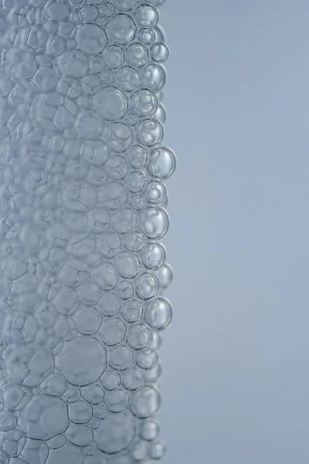
Biofilm is not a uniform slime. It is a structured, stratified microbial community where species arrange themselves by oxygen tolerance and substrate preference. The mass-transfer chain works in three coupled steps.
First, substrate — BOD as volatile fatty acids, NH₄-N, phosphate — diffuses from the bulk liquid into the biofilm. Oxygen diffuses the opposite way from the carrier-water interface (or the aerobic outer layer in oxygen-rich conditions). The flux is governed by Fick's law, and the effective rate depends on the concentration gradient across the boundary layer and the diffusivity inside the EPS matrix.
Second, bacteria metabolize what arrives. Heterotrophs oxidize organics to CO₂ and water. Nitrifiers — the slow-growing specialists (0.5–0.7 d maximum specific growth rate for Nitrosomonas, even lower for Nitrobacter) — oxidize ammonia to nitrite, then to nitrate. Below the oxic layer, in anoxic zones of thicker biofilm or during intermittent aeration phases, denitrifiers reduce nitrate to N₂. The high solid retention time on the carrier is what allows these slow growers to stay in the system — in CAS, they would wash out at typical HRT-to-SRT ratios.
Third, the biofilm is self-regulating. Carrier movement produces shear; excess growth sloughs off; new bacteria colonize the freshly exposed surface. The 2025 Bioresource Technology paper on comammox-dominated MBBRs showed the technology can run at oligotrophic conditions (~142.7 mg N/L/d nitrogen loading) and high dissolved oxygen (>6.0 mg O₂/L) with N₂O emission factors of ~0.06% — versus ~0.1% for a comparable sequencing batch reactor, a 46.1% reduction attributable to the absence of non-aerated settling and decanting phases (S2). That shear-driven renewal is also why biofilm recovers from toxic shock: the damaged outer layer is shed.
Key Design Parameters and What They Do to Performance
The numbers below are the ones you take into a vendor meeting. They are drawn from the open literature and normalized so the buyer can compare what each vendor is quoting.
| Parameter | Typical Range / Value | Source / Effect on Performance |
|---|---|---|
| Carrier fill fraction | 20% (industrial laundry) up to 70% (commercial systems) | S1 documents 20% K1 fill; Wikipedia notes up to 70% in high-density systems. Higher fill = more biomass, but more aeration energy and carrier-carrier abrasion. |
| Carrier material | HDPE, density ~0.95 g/cm³ | Preferred for plasticity, density, durability (per Wikipedia). |
| HRT | 4–24 h typical; 10 days documented in S1 laundry case | Shorter HRT for mid-strength industrial; longer for ammonia polishing or low-temperature duty. |
| Dissolved oxygen target | 2.0–4.0 mg/L (heterotrophic), >6.0 mg/L (comammox nitrification) | S2 ran >6.0 mg O₂/L for comammox enrichment; conventional nitrification design sits at 2–4 mg/L. |
| Organic loading rate | 2–15 g BOD/m³·d (aerobic MBBR) | Drives tank sizing; anaerobic MBBR handles 1–5 kg COD/m³·d for high-strength industrial streams. |
| BOD removal | 85–95% typical; 91% in S1 laundry case | S1: 441 → 39.67 mg/L at 20% K1 fill, 10-day processing time. |
| COD removal | 85–95% typical; 93.81% in S1 | S1: 910 → 56.3 mg/L. |
| NH₄-N removal | 70–95% at design HRT and DO | Function of temperature; rate drops sharply below 10–12 °C. |
Three operating modes are standard. Continuous flow is the default for steady industrial loads. Intermittent aeration cycles between aerobic and anoxic conditions, allowing simultaneous nitrification and denitrification in a single tank — useful for tight nutrient limits without a separate anoxic zone. SBR mode runs all treatment steps in a single reactor sequence and is sometimes used for smaller flows (per Wikipedia). Anaerobic MBBRs handle high-strength industrial wastewater, and pairing an anaerobic MBBR with an aerobic MBBR allows biogas recovery plus polishing in a two-stage train.
Normalization tip: when a vendor quotes removal percentages, ask for the fill fraction, HRT, influent BOD/COD, and temperature. Removal drops with shorter HRT, lower temperature, and higher influent strength; the S1 laundry numbers (91% BOD, 93.81% COD, 86.10% phosphate, 88.22% surfactant) were achieved at a 10-day processing time on 441 mg/L BOD influent — not on a 6-hour industrial pass.
MBBR vs MBR vs Conventional Activated Sludge
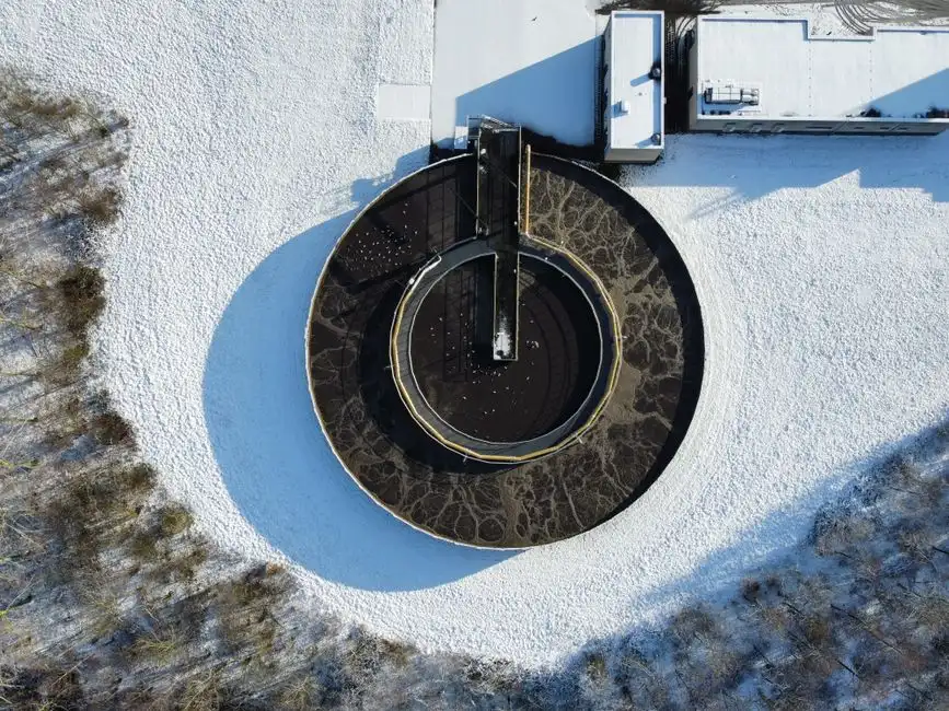
The decision is not which technology is "best" — it is which one matches your influent, your effluent target, and your operational tolerance. The table below normalizes the headline differences.
| Criterion | MBBR | MBR (Membrane Bioreactor) | CAS (Conventional Activated Sludge) |
|---|---|---|---|
| Effluent quality | BOD/COD <30 mg/L; NH₄-N <5 mg/L with nitrification design; cannot reach reuse-grade alone | Near-reuse quality (<1 µm filtration); BOD <5 mg/L, TSS <1 mg/L | BOD 20–30 mg/L; TSS 20–30 mg/L with good clarifier |
| Footprint | 30–50% smaller than CAS at equal load | ~60% smaller than CAS | Largest footprint; requires clarifier |
| Sludge handling | No sludge recycle; excess biofilm wasted directly | Sludge recycle + membrane fouling control | RAS/WAS loop; clarifier underflow |
| Sensitivity to toxic shock | Recovers but slowly (days to weeks) | Recovers in hours if membranes survive | Recovers in hours via wasting |
| CAPEX profile | Moderate (carriers + grid) | High (membranes + cassette + blowers) | Lowest (well-understood equipment) |
| OPEX profile | Aeration energy dominant | Aeration + membrane replacement + CIP chemicals | Aeration + sludge hauling |
| Retrofit friendliness | Excellent — often dropped into existing CAS basins | Poor — needs dedicated membrane tank | N/A (it is the baseline) |
The decision rule of thumb: specify MBBR for steady mid-strength industrial loads with BOD 200–1500 mg/L where nutrient removal and footprint matter but reuse quality is not required. Specify an MBR membrane bioreactor system when the effluent must meet reuse or very tight discharge limits, or when the site has zero tolerance for suspended solids carryover. Stay with CAS for very large municipal flows where budget is binding and the existing tank farm has decades of depreciation left. The most common MBBR specification, however, is a retrofit into an existing CAS basin — fill fraction is tuned to the new capacity target without building new tanks (per Wikipedia). For a deeper side-by-side on industrial influents, see this engineering brief on MBR vs conventional activated sludge for mining and petroleum wastewater.
Where MBBR Fails and How to Plan Around It
Every biofilm reactor has the same two failure modes, and the buyer has to price them in before signing a PO. The first is bioclogging and headloss build-up — excess biofilm growth, debris accumulation, or chemical precipitation on the carrier surface and the retention sieve (per Wikipedia). The second is carrier loss: a damaged sieve, hydraulic surge, or a backflow event can flush the entire media inventory downstream. The mitigation is upstream screening (a rotary mechanical bar screen sized for peak flow), redundant retention sieves, and continuous flow monitoring on the outlet. Equalization upstream also buffers the toxic-shock event, which is the third failure mode: biofilm recovers from inhibitory compounds but does so over days, not hours, because the sloughed biomass takes time to regrow.
The fourth, often overlooked, is cold-weather performance. Nitrification rate roughly halves for every 10 °C drop, and the curve gets steep below 10–12 °C (cf. S5 references on low-temperature operation). The mitigations are: design longer HRT into the basin, use intermittent aeration to maintain activity at the lower metabolic rate, or accept seasonal NH₄-N excursions and design the discharge permit around them. For nutrient-tight sites in cold climates, this is often the deciding factor that pushes the specification toward MBR or a sidestream anammox stage.
Frequently Asked Questions About How MBBR Works
What is an MBBR and who invented it?
An MBBR is a biofilm wastewater treatment process in which bacteria grow on free-floating HDPE plastic carriers mixed through an aerated tank. It was developed by Prof. Hallvard Ødegaard at the Norwegian University of Science and Technology in the late 1980s; the first full-scale plant started in Norway in 1985 and the technology was commercialized by Kaldnes Miljöteknologi, now AnoxKaldnes (Veolia Water Technologies) (per Wikipedia).
How much BOD and COD can MBBR remove?
Typical MBBR designs achieve 85–95% BOD and COD removal. The Tanjungpura University laundry case study documented 91% BOD removal (441 → 39.67 mg/L) and 93.81% COD removal (910 → 56.3 mg/L) at 20% Kaldnes K1 fill, 15-day seeding, and 10-day processing (S1).
What is the difference between MBBR and MBR?
An MBBR grows biofilm on plastic carriers with no membrane and produces BOD/COD effluent typically under 30 mg/L. An MBR couples activated sludge with a submerged membrane (pore size <1 µm) to produce near-reuse-quality effluent with BOD under 5 mg/L and TSS under 1 mg/L, at the cost of membrane replacement and fouling control.
Can MBBR be added to an existing activated-sludge tank?
Yes — this is the most common retrofit. The MBBR media is added to an existing aeration basin and the fill fraction (20–70%) is tuned to the new capacity target without constructing new tanks (per Wikipedia). For smaller decentralized sites, an underground package sewage treatment plant can integrate MBBR carriers into a factory-built unit.
Does MBBR produce less N₂O than other nitrogen-removal systems?
A comammox-dominated continuous-flow MBBR emitted ~0.06% of the incoming nitrogen as N₂O versus ~0.1% for a comparable sequencing batch reactor — a 46.1% reduction driven by the absence of non-aerated settling and decanting phases in the continuous-flow configuration (S2, Bioresour Technol, 2025). For sites subject to greenhouse-gas reporting, that delta is a real, auditable number.
Further Reading
- hospital wastewater treatment compliance and equipment selection
- inclined plate settler working principle and TSS removal
Frequently Asked Questions
How does an MBBR work step by step?
An MBBR process utilizes thousands of polyethylene biofilm carriers operating within an aerated or mechanically mixed wastewater basin. The system functions by providing a high surface area for microorganisms to attach and grow in a protected biofilm, which is kept in constant motion by air diffusers or mechanical mixers. As the wastewater passes through the reactor, the bacteria metabolize organic matter; the biofilm carriers are retained in the tank by stainless steel or wedge-wire sieves positioned at the outlet, ensuring the biomass remains in the system without the need for sludge recirculation.
What is the difference between MBBR and MBR?
The primary difference lies in the biomass separation method: MBBR uses a biofilm attached to moving media and relies on downstream clarification for solids separation, whereas Membrane Bioreactor (MBR) technology uses suspended growth biomass and replaces secondary clarifiers with microfiltration or ultrafiltration membranes. While MBRs produce superior effluent quality by physically filtering out bacteria and solids, MBBR systems are generally less complex to operate, require no membrane cleaning cycles, and have a lower energy footprint due to the lack of transmembrane pressure requirements.
How much BOD and COD can an MBBR remove?
MBBR systems are highly efficient, typically achieving Biological Oxygen Demand (BOD) removal rates between 85% and 95% in municipal applications. Chemical Oxygen Demand (COD) removal is also significant, with typical efficiencies ranging from 75% to 90% depending on the specific loading rates and hydraulic retention time. High-rate MBBR configurations can handle organic loading rates (OLR) exceeding 30-50 g BOD/m²/day, depending on the specific surface area of the media selected.
Can an MBBR be added to an existing activated sludge tank?
Yes, MBBR technology is frequently used for "IFAS" (Integrated Fixed-film Activated Sludge) upgrades, where biofilm carriers are added to existing activated sludge tanks to increase capacity without increasing the tank volume. By installing retention screens at the outlet and filling 30% to 60% of the tank volume with media, a facility can increase its total biomass concentration, allowing the plant to handle higher organic loads or achieve nitrification within the same footprint as the original aeration basin.
What are the disadvantages of MBBR systems?
The main disadvantages of MBBR include the potential for media clogging or screen blinding if the influent screening is inadequate, and the requirement for robust solids separation in the downstream secondary clarifier, which is not assisted by the process itself. Additionally, the initial capital cost for high-quality polyethylene media can be significant, and the system requires careful hydraulic design to ensure the media remains evenly distributed throughout the tank to avoid "dead zones" where treatment efficiency would drop.