What a Nanofiltration Maintenance Program Actually Covers
A practical nanofiltration system maintenance guide in 2026 relies on a three-tier protocol: (1) daily instrumentation checks of feed pressure, differential pressure, permeate flow, and permeate conductivity; (2) monthly clean-in-place (CIP) using pH 2 acid and pH 11–12 alkaline cycles, matched to the fouling type; and (3) annual membrane condition assessment via normalized flux and normalized salt passage trending. NF operates at 4–30 bar — well below the 10–80 bar window of reverse osmosis — and rejects 1–10 nm contaminants through a 200–1,000 Dalton equivalent pore, so maintenance centers on protecting that narrow window (per waterandwastewater.com). Membranes in industrial service are predominantly polyamide thin-film composite, with cellulose acetate still in older softening skids; chemical compatibility is not interchangeable, and the alkaline cleaning pH ceiling is typically 12 for polyamide because the amide bond hydrolyzes above that. The program below provides numbered steps the operator can adopt immediately.
Daily and Weekly Operating Checks: The NF Dashboard
Every NF dashboard must display four parameters: feed pressure, differential pressure (dP) per vessel, permeate flow, and permeate conductivity. The operating envelope requires feed pressure at 4–30 bar, dP per vessel flat against the commissioning baseline, permeate flow within ±10% of the temperature-corrected setpoint, and permeate conductivity tracking feed conductivity at the expected rejection ratio (waterandwastewater.com lists pressure, temperature, pH, and flow as the critical operational parameters). A 15% rise in dP per vessel is a fouling flag, not a tolerance band; log it and start planning a CIP. Two normalized values drive every trend line: normalized flux (current permeate flow ÷ feed flow, temperature-corrected to 25 °C and divided by the clean-membrane baseline recorded at commissioning) and normalized salt passage (permeate conductivity ÷ feed conductivity, divided by the same baseline). Temperature compensation matters because feed water temperature shifts flux by 2–3% per °C; absolute values mislead, but trends do not. Add a daily Silt Density Index (SDI) log from the cartridge filter outlet — a creep from 3 to 5 is the earliest signal that pretreatment is drifting before flux moves.
| Parameter | Typical NF Setpoint | Alarm / Action Threshold |
|---|---|---|
| Feed pressure | 4–30 bar (per waterandwastewater.com) | ±10% from commissioned baseline |
| Differential pressure per vessel | Flat against commissioning | +15% rise → schedule CIP |
| Permeate flow | Temperature-corrected to 25 °C | Normalized flux drop ≥10–15% → CIP |
| Permeate conductivity | Tracks feed at expected rejection | Normalized salt passage +15–20% → investigate |
| Feed water temperature | 15–30 °C typical | Compensate 2–3% flux/°C in trend log |
| SDI at cartridge outlet | < 5 (NF feed target) | SDI > 5 → pretreatment review |
Pretreatment Is Half the Maintenance Job
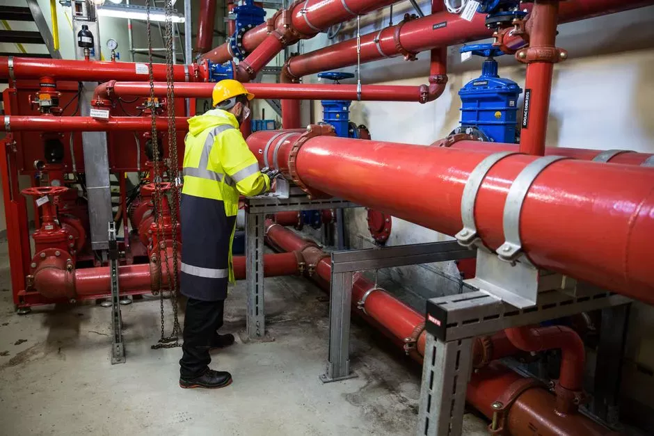
Most NF fouling starts upstream, and the pretreatment chain — typically 5 µm cartridge prefiltration, antiscalant dosing, and pH adjustment — prevents more cleanings than any CIP cycle will ever recover (waterandwastewater.com lists cartridge prefiltration and antiscalant/pH dosing as standard NF skid equipment). The SDI target at the NF feed is < 5 for reliable operation, with < 3 preferred on high-recovery or WWTP effluent polishing duty. Antiscalant selection for NF differs from RO: because operating pressure is lower and recovery targets are typically 70–85%, divalent-ion-heavy feeds (calcium, sulfate, carbonate) drive the dose, and a wider range of antiscalants is compatible than on a high-recovery RO train. Feed pH adjustment to 6.0–7.0 reduces silica scaling risk and improves polyamide rejection stability across the operating window. On a WWTP effluent polishing skid — the application Schrader's University of Twente thesis evaluates for direct NF reclamation — the pretreatment chain must absorb variability from the upstream biological and tertiary stages, and the maintenance program must respect that variability (Schrader, 2026, doi:10.3990/1.9789036523325). Operators running antiscalant and pH trim on a swing feed should look at a PLC-controlled antiscalant and pH dosing system tied into the SDI logger, and protect the cartridge stage with a rotary mechanical bar screen ahead of any open-intake or reuse-water feed.
CIP Chemistry and Procedure: A Field-Ready Recipe
CIP follows a normalized flux decline, not a calendar date; the trigger is a 10–15% drop in normalized flux or a 15% rise in dP per vessel, whichever comes first. The field-ready sequence is: (1) flush with permeate to displace feed; (2) alkaline wash at pH 11–12 with a non-ionic surfactant (e.g., 0.1–0.2% SDS or equivalent) for 60 minutes at 30–35 °C to remove organics and biofilm; (3) soak 1–2 hours; (4) acid wash at pH 2 with citric acid (preferred for calcium scale) or hydrochloric acid at 25–30 °C to dissolve carbonate and metal-oxide scale; (5) final permeate flush to neutral pH. Match the chemistry to the fouling type: organics and biological fouling respond to alkaline + surfactant, calcium carbonate responds to acid, silica scale needs high pH at elevated temperature (often pH 12–13 with a hot 35 °C soak), and biological fouling on tough feeds benefits from alternating alkaline + non-oxidizing biocide with the acid step. Temperature is a lever: 30–35 °C on the alkaline cycle and 25–30 °C on the acid cycle improve cleaning without breaching the membrane's chemical limits. A properly matched CIP typically recovers 85–95% of design flux; a water flush alone leaves you at 60–70%. Frequency runs every 1–3 months on a well-pretreated train, monthly on a challenging feed such as direct WWTP effluent polishing (waterandwastewater.com notes regular maintenance schedules, including chemical cleaning, as standard NF practice).
| Fouling Type | CIP Chemistry | pH | Temperature | Soak / Contact |
|---|---|---|---|---|
| Organics / oil | Alkaline + non-ionic surfactant (0.1–0.2%) | 11–12 | 30–35 °C | 60 min circulation + 1–2 h soak |
| Calcium carbonate / sulfate scale | Citric acid (preferred) or HCl | 2 | 25–30 °C | 60 min circulation |
| Silica scale | High-pH alkaline at elevated temperature | 12 (polyamide ceiling) | 35 °C | 2–4 h soak |
| Biological / biofilm | Alkaline + non-oxidizing biocide, alternating with acid | 11–12 then 2 | 30–35 °C then 25–30 °C | 60 min each step |
| Metal oxide (Fe, Mn) | Citric or sulfamic acid | 2–3 | 25–30 °C | 60 min circulation |
Membrane Replacement: When Cleaning Is No Longer Enough
Three objective triggers define the replacement decision and stop the operator from over-cleaning a dead element. (1) Normalized flux cannot be recovered above 75% of the clean-membrane baseline after a properly matched CIP. (2) Normalized salt passage has risen more than 15–20% from baseline, indicating irreversible surface damage or compaction. (3) Mechanical damage — telescoping, glue-line failure, or O-ring failure — is visible on inspection or inferred from a sudden conductivity excursion. The standard industrial NF life envelope is 3–7 years; shorter on WWTP effluent polishing duty where feed variability is high, longer on steady softening duty with tight pretreatment (waterandwastewater.com frames lifespan as a function of usage, maintenance, and water quality). The cost logic is straightforward: 1–2 failing elements in a train older than 4 years usually justify a full stage replacement, as the remaining elements are near the same wear point and the labor cost of a second changeout within 12 months is rarely justified. This decision requires a clean commissioning baseline on file, making the daily dashboard non-negotiable. Source HydropureWater replacement NF and RO membrane elements matched to the original spec sheet when the changeout is scheduled, not when the train is already offline.
Building the Annual Maintenance Calendar
Following a structured calendar ensures the system remains within its optimal operating window. Daily: dashboard walk-through (feed pressure, dP, permeate flow, conductivity), SDI log at the cartridge outlet. Weekly: instrument calibration verification on the conductivity and flow meters. Monthly: CIP if KPI-triggered, cartridge filter ΔP check, normalization of the last 30 days of data. Quarterly: antiscalant dose review against feed water analysis, CIP effectiveness review (compare recovered flux to the 85–95% target), seal and valve inspection. Annual: membrane autopsy on a sacrificial element from the lead vessel, pump and valve service, full normalization trend review against the commissioning baseline. Larger plants with instrumented operation and a structured program can run NF close to its design limits and capture the energy advantage over reverse osmosis (waterandwastewater.com). The skid sits downstream of biological, MBR, or DAF stages, and the NF maintenance program must absorb upstream variability rather than assume a steady feed. Cross-link routine biological-stage work to the biological-stage fouling field guide and upstream solids handling to the anaerobic digester maintenance guide so the entire train remains synchronized.
| Frequency | Task | KPI / Output |
|---|---|---|
| Daily | Dashboard walk-through (Pfeed, dP, Qperm, cond), SDI log | Normalized values within ±10% of baseline |
| Weekly | Instrument calibration check on conductivity and flow | Calibration drift < 2% |
| Monthly | CIP if KPI-triggered; cartridge ΔP check; 30-day normalization | Recovered flux 85–95% of design |
| Quarterly | Antiscalant dose review; CIP effectiveness review; seal/valve inspection | Dose matches feed Ca/SO4/SiO2 |
| Annual | Sacrificial element autopsy; pump/valve service; full trend review | Replace decision against 75% flux / 15–20% salt-passage triggers |
Frequently Asked Questions
How often should I CIP an industrial NF train?
CIP is KPI-triggered, not calendar-triggered; schedule a cleaning when normalized flux drops 10–15% from baseline or differential pressure per vessel rises 15%. On a well-pretreated industrial NF train, this is typically every 1–3 months; on a WWTP effluent polishing duty, monthly is common.
What is the difference between normalized flux and normalized salt passage?
Normalized flux is current permeate flow divided by feed flow, corrected to 25 °C and divided by the clean-membrane baseline. Normalized salt passage is permeate conductivity divided by feed conductivity, divided by the same baseline. Flux indicates production volume, while salt passage indicates rejection efficiency; the two trend together to distinguish fouling (flux down, salt passage flat) from membrane damage (flux down, salt passage up).
What SDI should I target at the NF feed?
Target SDI < 5 at the cartridge filter outlet for reliable NF operation, with SDI < 3 preferred for high-recovery systems and WWTP effluent polishing. A creep from 3 to 5 in the daily SDI log is the earliest signal that pretreatment is drifting before flux responds.
When is an NF element beyond cleaning and due for replacement?
Replace when normalized flux cannot be recovered above 75% of the clean-membrane baseline after a properly matched CIP, when normalized salt passage has risen more than 15–20% from baseline, or when mechanical damage (telescoping, glue-line failure) is visible on inspection. Standard industrial NF life is 3–7 years depending on feed and