The Brine Problem Most Fab Utilities Underestimate
TSMC reported 101 million m³ of water consumed in 2023, and industry projections point to fab water demand roughly doubling by 2035 (beta.co.id, 2026). That macro pressure is colliding with a regulated gap that has widened. Raw HF-etch wastewater commonly runs 250–1,500 mg/L fluoride against typical discharge limits near 15 mg/L, and Class 1–2 receiving-water rules in jurisdictions like Indonesia, Taiwan, and Korea push metals and fluoride into the ppb range (beta.co.id, 2026). Dilution is no longer a defensible strategy when influent fluoride is 100x the limit.
Two streams dominate the decision. CMP slurry waste typically represents 30–40% of total fab wastewater volume with 500–2,000 mg/L colloidal SiO₂ (beta.co.id, 2026; IDE Tech, 2026), and HF-etch fluoride carries the regulatory weight. The rest of the fab's effluent — cooling tower blowdown, scrubber water, general rinse — flows around these two concentrated streams, but it is fluoride and silica that determine whether a membrane or a thermal system pays back. Brine hauling and Class I landfill surcharges in water-stressed regions (Arizona, Hsinchu, Gyeonggi) have been rising double-digit per year, and that single line item is the lever that flips high-recovery RO (HRRO) into full ZLD in most 2026 capital plans.
Why You Must Segregate Fluoride, CMP, and Plating Drains First
Segregated drains and a working chemical train are prerequisites for both HRRO and ZLD to function effectively. New fabs should target the Winbond benchmark of 20+ separated drain lines for HF, organics, acids, ammonia, and plating streams (beta.co.id, 2026). Segregation lets the utility dose each line for its specific precipitant rather than chasing a moving target in a combined equalization tank.
The precipitation window is narrower than most engineers assume. At pH 8–9, copper drops ~95%, zinc ~89% at pH 7–8, iron ~97% at pH 5–6, and aluminum ~93% at pH 5–6; manganese is the recurring exception and typically needs pH ≥9–10 to break 16% removal (beta.co.id, 2026). Lime (Ca(OH)₂) or soda ash (Na₂CO₃) combined with FeCl₃ or polyaluminum chloride (PAC) drives Ca²⁺ + 2F⁻ → CaF₂(s) and coagulates colloidal SiO₂ into settleable flocs. Documented coagulation-UF performance delivers >90% F⁻ removal and effluent around 2.1 mg/L fluoride from feed in the hundreds of mg/L (beta.co.id, 2026).
Solids capture is the non-negotiable guard for any downstream membrane or crystallizer. A lamella clarifier for CaF₂ and metal-hydroxide settling or a DAF for light CMP floc and colloidal silica typically removes 95–99% of freshly formed TSS and cuts effluent TSS to 10–20 mg/L (beta.co.id, 2026). Skip this stage and the RO element lifetimes collapse, or the evaporator's heat exchanger fouls within weeks. For polishing before membranes, two-bed ion exchange (strong-acid cation in H⁺ form, then strong-base anion in OH⁻ form) can slash residual conductivity by 90%+, but it is the upstream chemistry, not the polisher, that determines whether the resin bed sees a stable feed or a slug event that exhausts it overnight.
High-Recovery RO: Where It Works, Where It Breaks
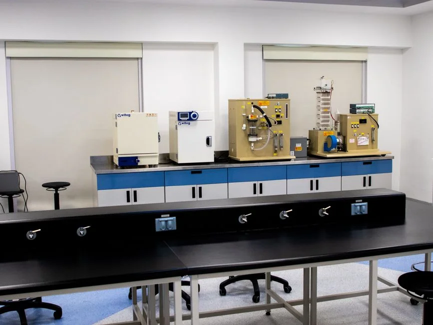
HRRO is RO staged with inter-stage booster pumps, high-shear thin-film composite elements, and brine recirculation. State-of-the-art fab systems achieve 85–90% recovery — and the 85–90% figure is the working ceiling for membrane-only operation, with a further 90% volume reduction reported when HRRO is paired with downstream polishing (IDE Tech, 2026; beta.co.id, 2026). RO rejection of dissolved solids exceeds 99%, but that 1% passage into permeate is exactly what enables upstream recycle and what concentrates the rejected species into a brine stream the plant still has to handle.
The membrane train breaks at three specific feed-chemistry cliffs. First, calcium fluoride scaling on the concentrate side becomes limiting when F⁻ in the feed exceeds roughly 1,000 mg/L, because antiscalants cannot fully suppress CaF₂ once ionic product exceeds solubility by that margin. Second, colloidal silica fouling is the dominant failure mode when SiO₂ climbs above ~1,200 mg/L in the concentrate, well below the 250–500 mg/L saturation that textbook calculations suggest because colloids foul the surface before they precipitate in the bulk. Third, pH excursions out of the 8–9 window re-dissolve the metals the upstream clarifier just removed, sending copper and zinc straight into the RO feed. A fab-grade industrial RO system for high-recovery duty should be specified with feed-specific antiscalant selection, not generic chemistry. The September 2026 study on material-specific fouling in fab UF/RO confirms that feed-stream-specific membrane and antiscalant pairing is now the controlling variable for recovery, not flux or pressure alone.
| Parameter | Operating envelope (HRRO) | Failure mode if exceeded |
|---|---|---|
| Feed fluoride (F⁻) | ≤ 1,000 mg/L with antiscalant | CaF₂ scaling on concentrate side |
| Feed colloidal SiO₂ | ≤ 1,200 mg/L concentrate | Surface fouling, flux decline |
| Recovery | 85–90% practical ceiling | Permeate quality / scaling trade-off |
| Rejection (TDS) | > 99% | 1% passage into permeate (by design) |
| Energy intensity | 0.5–3 kWh/m³ permeate | Higher with multi-stage boost |
For a UF pretreatment for CMP colloidal silica, the spec is 0.01–0.05 µm pore size with regular CIP cycles, sized for the slurry load. Without that, the RO element replacement cadence shortens from a 3–5 year target to 12–18 months and the OpEx math falls apart.
Full ZLD: When the Brine Concentrator and Crystallizer Earn Their Keep
IDE Tech defines ZLD as a train of UF + RO + evaporation/crystallization + fractional electrodeionization, with the explicit goal of zero liquid discharge (IDE Tech, 2026). The recovery step-change is real: 85–90% for state-of-the-art HRRO versus >99% for ZLD, a 10–15 percentage-point gap that translates directly into brine volume per m³ of feed. On a 5,000 m³/day fab waste plant, that gap is the difference between 500–750 m³/day of concentrate to haul and 0–50 m³/day of solids to landfill.
The economic cliff sits in the energy intensity. Thermal evaporation and crystallization typically use 15–60 kWh/m³ of recovered water depending on brine strength and whether the system is mechanical vapor recompression (MVR) or thermal vapor recompression (TVR); RO uses 0.5–3 kWh/m³ — a 10–30x differential (IDE Tech, 2026; beta.co.id, 2026). For a regulator-permitted site where brine can be trucked out at modest cost, that energy gap alone disqualifies ZLD. For a zero-discharge mandate, that gap becomes irrelevant because hauling is no longer an option.
ZLD-specific risks deserve weight. Calcium sulfate and silica scale the evaporator tubes; HF and NH₃ carryover requires a scrubber; and the physical footprint is large enough to compete with cleanroom build-out, which is not a minor concern on a brownfield site. Emerging alternatives — membrane distillation, low-temperature evaporators, forward osmosis–nanofiltration hybrids — are the trend line that may compress the ZLD energy premium by 2027–2028. The current 2026 reality is that ZLD is the lowest-risk, highest-CapEx option and that operators should write the upgrade path into the HRRO plot plan from day one.
HRRO vs ZLD: The Decision Matrix Fab Utilities Actually Use
The matrix below anchors eight parameters that drive the HRRO-vs-ZLD choice on a real fab project. All figures are typical 2026 ranges, not vendor quotes, and should be refined against site-specific feed chemistry and a current hauling contract.
| Parameter | High-Recovery RO (HRRO) | Full ZLD |
|---|---|---|
| Water recovery | 85–90% | > 99% |
| Feed F⁻ tolerance | ≤ 1,000 mg/L with antiscalant | Effectively unlimited (post-precipitation) |
| CapEx per m³/day capacity | ~1x baseline | ~3–5x baseline |
| OpEx drivers | Membrane replacement + energy 0.5–3 kWh/m³ | Steam/electricity + antiscalant, 15–60 kWh/m³ |
| Brine volume (per m³ feed) | 10–15% (50–150 L) | 0–1% (0–10 L solids) |
| Mandate suitability | Class 1–2 with brine permit | Zero-discharge regions, PFAS-driven sites |
| Footprint | Compact, modular | Large; competes with cleanroom build-out |
| Time to permit / build | Months | 12–24 months |
The second cut is feed-chemistry thresholds. Below 500 mg/L F⁻ and 800 mg/L SiO₂, HRRO is unambiguously the lower-cost path. Between 500–1,500 mg/L F⁻, HRRO is still viable but the brine needs polishing or a hybrid thermal stage to keep hauling volumes inside the permit envelope. Above 1,500 mg/L F⁻, or anywhere a zero-discharge rule applies, full ZLD is the only defensible answer.
A worked example for a 5,000 m³/day fab waste plant: HRRO typically runs $3–6M CapEx and $0.25–0.60/m³ OpEx; ZLD typically runs $15–30M CapEx and $1.50–4.00/m³ OpEx. The break-even hauling cost sits at roughly $15–25 per m³ of concentrate — above that number, ZLD's higher CapEx becomes self-funding on OpEx savings (HydropureWater field data, 2026). On water-stressed sites with strong ESG mandates, water-reuse credits, and recovery incentives in Taiwan, Arizona, and Korea can shorten the payback by 1–3 years. For a deeper look at the ZLD capital case, the wafer-fab ZLD hybrid design and cost blueprint lays out the full 2026 economics. For context on the demand side, the SK Hynix fab water-reduction target for 2030 shows where the major memory players are heading.
Frequently Asked Questions
At what fluoride concentration does HRRO stop being viable for fab wastewater?
HRRO remains viable up to roughly 1,
Frequently Asked Questions
What is the difference between ZLD and high-recovery RO for semiconductor wastewater?
High-Recovery Reverse Osmosis (HRRO) is a separation process that concentrates dissolved solids into a brine stream while producing clean permeate, typically achieving recovery rates between 85% and 95%. Zero Liquid Discharge (ZLD) is a comprehensive facility-wide strategy that integrates thermal processes like evaporators and crystallizers to eliminate liquid waste entirely, converting the concentrate into solid salt cake for disposal.
How high can RO recovery go on fluoride and CMP wastewater before scaling kills it?
On fluoride-rich CMP wastewater, RO recovery is generally capped at 80% to 90% without advanced antiscalant dosing or inter-stage chemical softening. Because CMP streams contain high concentrations of silica and calcium fluoride (CaF2), exceeding these limits triggers rapid mineral scaling on membrane surfaces, which leads to irreversible flux decline and salt passage increases.
When does ZLD become cheaper than HRRO for a fab utility?
ZLD becomes the economically viable choice when local wastewater discharge regulations impose high "per-cubic-meter" surcharges exceeding $15–$25, or when water scarcity mandates a 100% recycling rate to maintain operations. While HRRO has lower capital expenditure (CAPEX) and energy requirements, ZLD provides a lower total cost of ownership (TCO) in regions where liquid discharge permits are restricted or prohibitively expensive due to strict environmental compliance costs.
Is zero liquid discharge mandatory for semiconductor fabs in 2026?
ZLD is not universally mandatory in 2026, but it is increasingly required by local environmental agencies in water-stressed semiconductor manufacturing hubs, particularly in parts of Southeast Asia, China, and the Southwestern United States. While not a global standard, many new fab constructions now include ZLD requirements as a condition for obtaining environmental impact assessment (EIA) approvals and municipal water usage permits.
What pretreatment is required before RO or ZLD on a fluoride CMP stream?
Effective pretreatment for fluoride CMP wastewater requires a two-stage approach: chemical precipitation using lime (calcium hydroxide) to reduce fluoride levels to below 20 mg/L via CaF2 formation, followed by coagulation, flocculation, and multi-media filtration or ultrafiltration (UF) to remove suspended colloidal silica and nanoparticles. Without these steps, the high silica and fluoride content will cause immediate fouling and scaling of downstream RO membranes or thermal evaporator heat exchangers.