What Counts as a Package Wastewater Treatment Plant
A package wastewater treatment plant is a pre-manufactured facility for small communities or individual sites. Typical flows are 0.002–0.5 MGD, most often 0.01–0.25 MGD (EPA 832-F-00-016, September 2000). Mechanical installation usually takes 2–6 weeks, then 2–4 weeks of biological commissioning before a performance test at design flow.
Common trains are extended aeration, sequencing batch reactor (SBR), oxidation ditch, contact stabilization, rotating biological contactor, and physical/chemical systems (Metcalf and Eddy, 1991, as cited in the EPA fact sheet). The generic process flow is screening, optional grinding, flow equalization, aeration, clarification, and disinfection, with return activated sludge (RAS) and waste activated sludge (WAS) loops tied back to the aeration chamber. The same installation logic applies whether the unit is above-grade, below-grade (such as the Underground Package Sewage Treatment Plant (WSZ Series)), or trailer-mounted. “Package” refers to the manufacturing approach, not the process: the reactor, clarifier, blowers, and controls arrive as one or two factory-built modules rather than as a stick-built concrete basin.
Package Plant Design Parameters You Need Before Installation Starts
Design parameters must be locked into the submittal package before the first excavator arrives. The most expensive field changes are always the ones discovered after the tank is on the truck. EPA benchmarks (EPA 832-F-00-016, 2000-09) bracket the technology by flow band, contact time, and effluent quality. Most state discharge permits tighten the effluent numbers rather than the hydraulic envelope.
| Parameter | Extended Aeration | SBR | Oxidation Ditch | MBR |
|---|---|---|---|---|
| Typical flow range (MGD) | 0.002–0.1 | 0.01–0.2 | 0.01–0.5 | 0.01–0.25 |
| Hydraulic contact time | 18–24 h | Batch (fill/react/settle/decant) | 18–24 h | 6–12 h + membrane |
| Target BOD5 (mg/L) | < 15 | < 15 | < 15 | < 5 |
| Target TSS (mg/L) | < 10 | < 10 | < 10 | < 1 |
| MLSS operating range (mg/L) | 2,000–4,000 | 2,500–4,000 | 3,000–5,000 | 6,000–12,000 |
| Start-up seed sludge | From donor plant (EPA) | From donor plant | From donor plant | From donor plant |
| CAPEX benchmark (per gallon treated) | USD 4–6 (EPA, 2000-09) | USD 5–8 (typical) | USD 5–9 (typical) | USD 8–14 (typical) |
For buried units, confirm the design burial depth, traffic loading (H-20 if vehicles will pass above), and seasonal high groundwater table against the tank structural drawing before the foundation is poured. A buried tank in a high water table without hold-down provisions is the single most common post-install failure mode. Buoyancy calculations belong in the submittal, not in the change-order log. Most plants we size for rural campuses run at the lower end of the extended-aeration band, around 0.01–0.05 MGD.
Step 1: Pre-Mobilization Engineering and Permitting
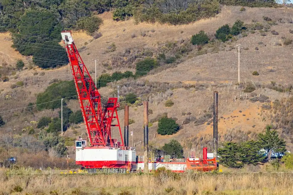
Pre-mobilization is the cheapest day of the project once the permit is in hand and the geotech report is signed. Run a geotechnical and groundwater investigation across the tank footprint. Document soil bearing capacity (typically 1,500–3,000 psf for packaged steel tanks on a concrete slab), seasonal high water table, and rock depth. Confirm the discharge permit and effluent limits with the controlling authority before ordering the tank. That authority may be state NPDES, Ontario ECA, EU 91/271/EEC, or the local equivalent. Re-permitting a non-compliant unit can cost more than the original equipment.
Freeze the process flow diagram, P&ID, and electrical single-line as “Issued for Construction” and stop the design churn. Validate site access for the delivery truck (often 20–30 tonnes for a packaged unit), the turning radius, crane reach, and overhead obstructions. The package plant engineering guide for Ethiopia walks through the access checklist for sites with tight rural approaches. Lock the seed-sludge source now too: an arranged donor plant, a hauling contract, and a confirmed SVI reading on the day of transfer.
Step 2: Site Preparation, Excavation, and Foundation
Foundation work is the one stage where mistakes are buried and never recovered. Treat the civil scope as a precision activity rather than a dirt-moving activity. Excavate to the tank footprint plus 600–900 mm of working room on each side. Bench or shore the walls per OSHA 29 CFR 1926 Subpart P or the local equivalent. Pour a reinforced concrete slab or crushed-stone base sized to the tank drawings. Provide a 25–50 mm sand bedding layer under buried units to prevent point loading on the shell.
Address buoyancy explicitly. A buried tank in a high water table needs either a concrete hold-down slab, ground anchors, or a calculated thickness of soil overburden. Set influent, effluent, and any electrical conduit penetrations during the pour. Sleeve every penetration to allow differential settlement between the tank and the pipe. A pre-pour layout walk with the installing contractor and the manufacturer's rep catches about 90% of the field-coordination errors before the concrete shows up.
Step 3: Tank Delivery, Lifting, and Setting
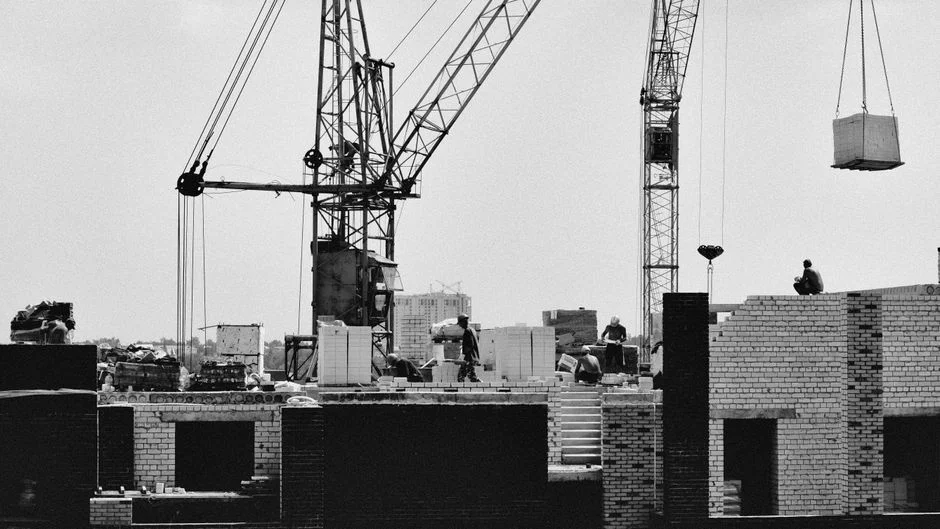
Tank setting is the one chance to do it right. The warranty usually requires documented evidence that the lift and level conformed to the manufacturer's procedure. Use only the certified lifting points shown on the shop drawing. Never lift a packaged unit by piping, diffuser drops, the access hatch frame, or the blower piping. Set the tank level to within ±6 mm across the long axis. Shim with non-corrosive stainless or composite shims.
For above-grade packages, including trailer-mounted HydropureWater MBR systems, verify that the trailer jack stands sit on a compacted gravel pad, not asphalt or soft soil, and chock the wheels. Document the set with photos and a level survey before any backfill. The as-built record protects the warranty and answers the regulator's questions. Compare the install plan against an actual containerised deployment like the containerised MBR project case study. That case shows how a factory-built module arrives, gets offloaded, and is tied into the hydraulic profile.
Step 4: Pipework, Hydraulic Profile, and Utility Hookups
Hydraulic short-circuiting causes most performance failures. It almost always traces back to pipework decisions made on Day 1. Match the influent pipe diameter to the design peak flow, typically 1.5× the average daily flow. Maintain a minimum 1% gradient to the headworks so the line stays clean between peak events. Equalize flow upstream of the aeration chamber if the peak hourly flow is more than roughly 2.5× the daily average. Without equalization, the aeration basin sees a daily BOD shock that the biology cannot buffer.
Provide an effluent flow-measurement device — a Parshall flume or magnetic flow meter — before the disinfection stage. That meter makes performance testing defensible and gives the operator a real number to trend. Route scum and the RAS/WAS lines with isolation valves and cleanouts at every change of direction. A screen ahead of the aeration chamber, such as a HydropureWater rotary bar screen, protects the downstream diffusers and is easier to service when installed with proper access. For a worked example of peak factors and I&I on a small subdivision, the 25,000 GPD package plant project case study shows the hydraulic profile end to end.
Step 5: Electrical, Controls, and SCADA Integration
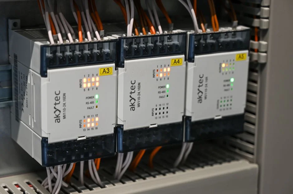
Controls work is where installs stall waiting for an electrician or a PLC programmer. Spell the electrical scope out before mobilization. Provide a dedicated circuit with a locked disconnect, surge protection, and a ground rod tested to less than 25 Ω. Confirm voltage and phase match the blower and pump nameplates to avoid the 230/460 V mix-up that burns a motor on Day 1. Install the PLC panel in a NEMA 4X or IP65 enclosure. Mount it with clear line-of-sight to the aeration tank and the access hatch so the operator can read the HMI while standing at the basin.
Land I/O for influent level, dissolved oxygen, RAS flow, and effluent turbidity. Verify SCADA tag mapping against the P&ID before energizing. Program DO setpoints at typically 1.5–2.5 mg/L in the aeration basin for an extended-aeration system. Back up the program to the engineer's archive the same day it is commissioned. Field crews that skip the tag-map check spend the first week chasing phantom alarms instead of tuning DO.
Step 6: Wet Commissioning with Seed Sludge
Biological start-up is the step that turns a steel tank into a working treatment plant. It runs on biology's clock, not the construction schedule. Fill the aeration chamber with clean water before introducing seed sludge. Seed at roughly 10–20% of the aeration volume from a healthy donor plant (per EPA guidance for extended-aeration units, EPA 832-F-00-016, 2000-09). Aerate continuously for 7–14 days. Target mixed-liquor suspended solids (MLSS) of 2,000–4,000 mg/L with a 30-minute settling ratio of 30–50% as the biomass establishes.
Begin feeding wastewater gradually — typically 25% of design load in week 1, 50% in week 2, and 100% by week 3 — to let the biomass acclimate to the actual waste stream. Do not run disinfection to drain during start-up. Route the effluent back to the headworks until BOD and TSS meet permit limits. Use a reliable chemical dosing system for the chlorination or dechlorination step once the effluent is in spec. Stabilization after seeding commonly takes two to four weeks before the plant holds a steady MLSS and settling profile.
Step 7: Performance Testing, Documentation, and Handover
The performance test is the artifact the regulator and the owner both want. It has to be defensible to a third-party reviewer. Run a 7-day performance test at design flow and collect 24-hour composite samples. Demonstrate the EPA extended-aeration benchmark of less than 15 mg/L BOD and less than 10 mg/L TSS, or tighter limits if the discharge permit requires it. Calibrate the effluent flow meter and any online probes against a manual reference. File the calibration certificates in the handover dossier alongside the as-built drawings, P&ID, PLC source code, O&M manual, spare parts list, and operator training records.
Schedule the 30-day and 90-day compliance checks before demobilizing the commissioning crew. The first three months are when latent defects actually show up — a cracked sleeve, a miscalibrated probe, or a RAS line that air-locks at peak flow. Owners who skip the 90-day revisit usually rediscover those defects during the first wet-weather event.
Installation Checklist and Cost Drivers
The decisions that move cost and schedule most are geotech quality, buoyancy hold-downs, crane access, permit timing, seed-sludge logistics, and electrical readiness. Use this short checklist before you release fabrication:
- Discharge permit and effluent limits frozen in writing
- Geotech report with seasonal high groundwater and bearing capacity
- Buoyancy calculation and hold-down method on the structural drawing
- Delivery path cleared for a 20–30 tonne truck and crane reach
- Seed-sludge donor plant and haul contract confirmed
- Electrical service voltage/phase matched to nameplates
- Performance-test plan and sampling lab booked for week of start-up +3
SBR, oxidation ditch, and MBR packages sit higher in the table above. Soft costs from late permits and redo civil work often exceed the equipment delta between process options.
Who This Is For / Next Step
Package plant installation guidance fits plant engineers, EPC contractors, and owners installing factory-built extended-aeration, SBR, oxidation-ditch, or MBR packages in the roughly 0.01–0.25 MGD band. Teams building large stick-built municipal plants above about 0.5 MGD should look to conventional activated-sludge design rather than a packaged module. If you need help matching burial depth, hydraulic profile, or start-up sequencing to a specific site, request a package plant installation review with your flow, effluent limits, and geotech notes attached.
Frequently Asked Questions
How long does package plant installation take?
Most plants reach mechanical completion in 2–6 weeks, followed by 2–4 weeks of biological commissioning before the performance test (HydropureWater field data, 2026). Soil conditions, weather, and the speed of the discharge permit push the schedule more than the equipment delivery does. Locking geotech and seed sludge before mobilization is what keeps projects inside that window.
What permits are needed before a package plant is delivered?
You need a discharge permit (NPDES, Ontario ECA, EU 91/271/EEC, or local equivalent), building and electrical permits, and in some jurisdictions a Hold Harmless agreement covering the discharge. Locking the permit before ordering the tank avoids scope creep. Effluent limits on that permit should drive process selection, not the other way around.
Can a package plant be installed below the water table?
Yes, but the tank has to be designed for buoyancy with a concrete hold-down slab, ground anchors, or proven soil overburden before backfill. Seasonal high groundwater belongs in the geotech report, not as a field discovery. Units such as the HydropureWater WSZ underground package plant still need those hold-down provisions when the water table rises into the excavation.
How much seed sludge does start-up need?
Seed at roughly 10–20% of aeration volume from a healthy donor plant. Then aerate 7–14 days toward MLSS of 2,000–4,000 mg/L for extended-aeration units (EPA 832-F-00-016, 2000-09). Ramp influent load from about 25% to 100% over three weeks. Recycle under-performing effluent to the headworks until BOD and TSS meet the permit.
What effluent quality should a performance test prove?
Demonstrate less than 15 mg/L BOD and less than 10 mg/L TSS over a 7-day test at design flow for extended-aeration packages. Use tighter limits if the discharge permit requires them (EPA 832-F-00-016, 2000-09). Use 24-hour composites and a calibrated effluent flow meter. File calibration certificates with the as-built package before handover.