What an MVR Evaporator Is and Why Commissioning Differs from a Steam-Effect Unit
MVR evaporator installation and commissioning is a phased site protocol: confirm foundation and utilities, rig the labeled skidded sections, reconnect the four primary lines (feed, residue, distillate, cleaning) and main power, run a factory-style pre-commissioning on water, then ramp gradually from water trials to real wastewater while monitoring compressor load, ΔT, and distillate conductivity. A typical salt-solution retrofit documented on Scribd reached 9,900 MT/year steam savings and a 6.7-month payback once the MVR was commissioned (source: Scribd case study, 2026).
Mechanical vapor recompression (MVR) reuses the vapor boiled off the process liquid as its own heating medium. A centrifugal or roots-type vapor compressor raises the vapor from the evaporator body to a higher saturation temperature; that compressed vapor condenses inside the heat exchanger, giving up latent heat to the recirculating feed, and the condensate becomes the distillate stream (per Baihuipu, 2026). The only utility inputs are electricity for the compressor and recirculation pumps, plus a small startup heating step — the Scribd case study explicitly notes "no utility steam input is required for evaporation, apart from an initial heating at startup."
Two commissioning consequences follow. First, there is no large live-steam header, condensate return, or boiler tie-in to validate; piping scope collapses to four process lines plus power. Second, the vapor compressor is the dominant rotating equipment and dictates the startup sequence — its vibration, amp draw, and VFD curve must be characterized before the unit goes on real feed. This guide covers skid-type packaged MVRs (ENCON-style) following the phased logic buyers can hand to a contractor; falling-film plus recompression configurations with an external separator and ejector train follow the same sequence but add vacuum-train checks.
Documentation should mirror the structure used for thermal-process commissioning under BSI standards (e.g., the BS EN 15287 family for design, installation, and commissioning cited by BSI, 2026) — design freeze, factory acceptance, site acceptance, and as-built handover.
Phase 1 — Pre-Shipment: Factory Acceptance Test (FAT) Before the MVR Leaves the Workshop
A witnessed FAT locks the performance baseline on paper so any on-site deviation can be measured against it. Run this test at the vendor's shop before the skids are disassembled for transit, and treat the FAT report as the single most important document in the commissioning file.
The buyer's engineer should witness and sign off on the following:
- Compressor vibration and amp draw at design RPM, captured with a portable analyzer and compared against the API 617 / vendor acceptance band (typically ≤4.5 mm/s RMS on the bearing housing for a small-frame centrifugal).
- Heat-exchanger bundle hydrostatic test at 1.3× design pressure for 30 minutes, with no pressure drop on the chart recorder.
- Instrumentation loop check on level probes, pressure transducers, temperature RTDs, and conductivity meters — confirm 4–20 mA signals at 0%, 50%, and 100% of range.
- A water run through the pretreatment skid with the chemical dosing panel online; record flows, pressures, and stroke lengths on each dosing pump.
- Coating thickness (DFT) on all wetted carbon-steel surfaces, lifting-point certification, and anti-corrosion packing for sea/road transit (per Baihuipu's shipment inspection protocol, 2026).
Capture as-left settings: set points on level probes, pressure transducer ranges, VFD parameters (ramp, min/max Hz, current limit), and CIP dosing pump strokes. These numbers become the commissioning baseline.
Deliverables the buyer should demand before release: a signed FAT report with photos, a signed I/O list, the P&ID with redlines, a lubrication and chemical startup kit checklist, and the MVR boundary drawing that shows exactly what the vendor pre-wired versus what the buyer must connect.
| FAT activity | Buyer action | Vendor action |
|---|---|---|
| Compressor run at design RPM | Witness, record amps and vibration | Operate, provide test chart |
| HX bundle hydrostatic test | Witness 1.3× design, 30 min hold | Set up, certify |
| I/O loop check | Sign I/O list line-by-line | Drive signals, log mA |
| Pretreatment skid water run | Confirm flows/doses | Run, log data |
| Shipment inspection | Approve packing, photo-record | Document DFT, lift points |
Phase 2 — Site Preparation Before the Truck Arrives
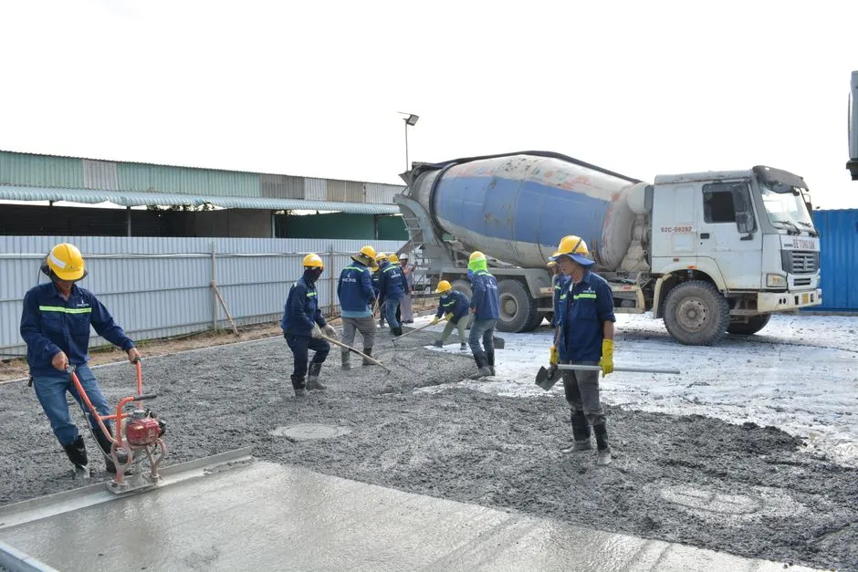
Site preparation runs in parallel with transit; a 4–6 week transit window is the buyer's last chance to get civil and utilities right. Skids that arrive to an unprepared pad sit on the truck until someone pays demurrage.
Civil work: foundation pads sized to the labeled skidded sections on the vendor's GA drawing, with anchor bolts set to template and a clear lay-down area for offload. Confirm a rigger/forklift path with the correct lift capacity — the evaporation section on a typical packaged MVR can run 2–5 tonnes and is the heaviest single lift (per ENCON installation note, 2026).
Utilities: confirm the electrical feed reaches the main disconnect behind the operator interface panel at the correct voltage and short-circuit rating; stub in compressed air for pneumatic valves, CIP water at the design flow and pressure, and chemical dosing lines tied to the dosing panel if a cleaning-solution tank is in scope. For pH-controlled pretreatment, a skid-mounted skid-mounted automatic chemical dosing system keeps the lime/caustic feed inside the MVR boundary and reduces field wiring.
Piping tie-ins to be stubbed in and hydrostatically tested before the skids arrive: feedstock from the equalization tank or sump to the wastewater feed connection, residue line to the residue tank, distillate to the distillate holding tank, and cleaning-solution feed to the cleaning-solution line (per ENCON connection list, 2026).
Safety: mark hot-surface zones, install ladders and walkways so elevated valves, sensors, HX, blowers, manways, and mist pads are reachable, and stage OSHA hot-surface insulation blankets for the flanges, fittings, and HX that will be reassembled on site (per ENCON, 2026). Confirm lockout/tagout points and a confined-space entry plan for any vessel manway work.
| Site prep workstream | Pre-arrival deadline | Owner |
|---|---|---|
| Foundation pads, anchor bolts | 2 weeks before truck | Buyer / civil contractor |
| Power to main disconnect | 1 week before truck | Buyer / electrical contractor |
| Process piping stubs, hydrotest | 1 week before truck | Buyer / piping contractor |
| Hot-surface insulation blankets staged | Day of rigging | Buyer safety / vendor |
| LOTO, confined-space, hot-work permits | Day of rigging | Buyer EHS |
Phase 3 — Mechanical Installation: Rigging, Alignment, and Reassembly of the Skidded Sections
Mechanical install is the phase most likely to slip if sequencing is not controlled. A typical packaged MVR arrives in 4–6 labeled sections: feed/pretreatment, evaporator body with separator, vapor compressor, distillate/condensate, and CIP. Each is rigged individually, reassembled, and aligned before any piping is torqued.
Sequence the crew can execute in one shift per skid:
- Offload using the labeled lift points; a rigger is required for the evaporation section because of its mass and the need to preserve the orientation of the vapor compressor and separator bodies (per ENCON, 2026).
- Set the skid on the foundation, snug the anchor bolts, and verify level with a digital level before any grout goes in.
- Reassemble the labeled sections mechanically: bolt up flange joints with new gaskets, and fit the metallic-sheathed insulation with metal retaining bands (per ENCON, 2026).
- Reconnect the four primary plumbing lines and the cleaning-solution line exactly as enumerated: feedstock, residue, distillate, cleaning, plus main power at the disconnect behind the operator panel.
- Align the vapor compressor and recirculation pump shafts to vendor tolerances with a dial indicator or laser system, then torque anchor bolts and grout baseplates only after alignment is signed off.
- Fit removable insulation blankets on all flanges, fittings, and HX to keep the unit OSHA-compliant near hot surfaces (per ENCON, 2026).
For battery-recycling or metal-finishing ZLD trains where the evaporator follows a precipitation skid and a plate and frame filter press for sludge dewatering, the filter press is usually commissioned in parallel and the underflow cake is the feed to the evaporator; coordinate the two hand-offs so the evaporator never idles on a slurry it cannot process. If the pretreatment train is a lamella clarifier upstream, follow the same mechanical sequence documented in the lamella clarifier installation and commissioning protocol and then mechanically tie in the clarifier overflow to the MVR feed.
Phase 4 — Electrical, Instrumentation, and Pre-Commissioning Loop Checks
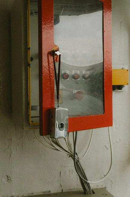
Energization is the moment a paper skid becomes a running machine, and it is also the highest-risk step for the E&I team. Work from the main disconnect outward, with the vapor compressor locked out until phase rotation is confirmed and the LOTO procedure is posted at the panel.
Energize from the main disconnect behind the operator interface panel; verify phase rotation on the vapor compressor, recirculation pump, and concentrate discharge pump with a phase-rotation meter before the first bump (per ENCON, 2026). Loop-check the pre-wired devices inside the MVR boundary: feedstock pump, recirculation pump, vapor compressor, concentrate discharge pump, level probes, and pressure transducers — all should arrive pre-wired and pre-plumbed, so the field loop check is essentially a point-to-point continuity and range check rather than a from-scratch wiring job (per ENCON, 2026). Confirm the SCADA/HMI has trending and alarms enabled, and stand up remote access if the vendor's remote engineering support is in scope (per Baihuipu, 2026).
For sites integrating the MVR with an existing ZLD train — typically equalization, precipitation, clarification, evaporation, and optional crystallization — the architecture mirrors the IC wastewater water reclaim ZLD blueprint at 98%+ recovery, and the same SCADA tags (flow, pH, conductivity, kW) should be exposed on the plant historian.
| Parameter | Pre-commissioning target | Acceptance evidence |
|---|---|---|
| Body vacuum (falling-film) | -0.06 to -0.085 MPa gauge | Transducer reading vs. FAT baseline |
| Compressor amp draw at design RPM | Within ±10% of FAT baseline | Clamp-meter log, 30-min steady state |
| Distillate conductivity | < 50 µS/cm on water trial | Online meter + grab sample |
| ΔT across HX | 2–6 °C approach, per design | RTD pair, log every 5 min |
| CIP sequence verification | Acid → rinse → caustic → rinse steps pass | Valve position feedback, conductivity profile |
| Level-probe interlocks | High-high trip on body level, no false trips | Step-test each probe |
Phase 5 — Water Trial: The First 48 to 72 Hours of Commissioning
Water trial is the engineer's chance to find leaks, tune loops, and prove interlocks on a forgiving medium before real wastewater touches the heat-exchange surfaces. Treat the first 72 hours as a controlled experiment, not a production run.
Run on clean water first, then gradually introduce real wastewater while monitoring metal-removal efficiency and distillate quality; ramp slowly so the precipitation chemistry and evaporator load stabilize before full throughput (per Baihuipu, 2026). Track distillate conductivity as the primary "is the loop clean" indicator; an MVR distillate is low in dissolved solids and is reused for washing, cooling, or make-up water (per Baihuipu, 2026). Verify circulating velocity is high enough to suppress scaling on the heat-exchange surfaces — particularly important where chlorides are high and titanium or special-alloy surfaces are in use, and the design typically targets 1.5–2.5 m/s on the tube-side (per Baihuipu, 2026).
Use the FAT baseline as the comparison reference. If compressor amps drift more than 10% upward at the same RPM, suspect a fouling trend or a vapor-side superheat issue and stop the run to inspect. Lock the VFD curves on the compressor and the recirculation pump only after 24 hours of stable operation on water.
Phase 6 — Performance Acceptance, Documentation, and Handover
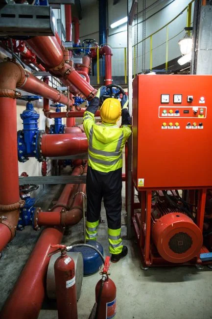
SAT is the contractually binding test. Run it at design throughput on real wastewater, comparing distillate conductivity, compressor kWh per cubic meter of water evaporated, and salt concentration against the FAT baseline and design guarantee (per Baihuipu, 2026). Document the steady-state window — typically a 4–8 hour hold at design feed rate — and sign the SAT protocol jointly with the vendor.
Hand over the as-built P&ID, the I/O list, the updated settings, the lubrication schedule, and a preventive-maintenance plan covering probe calibration, scale cleaning, compressor oil checks, and gas detection in chemical rooms (per Baihuipu, 2026). Train the local operations team on the CIP sequence, the hot-surface insulation blanket locations, and the ladder/walkway routes to elevated valves, sensors, HX, blowers, manways, and mist pads (per ENCON, 2026).
For sites that pair the MVR with disinfection of the recovered distillate before recycling, an on-site chlorine dioxide generator sized to the distillate flow gives a closed microbiological loop and avoids storing commercial hypochlorite on site. Reality check on economics: the Scribd salt-solution case study reports 9,900 MT/year steam saved on an 80-lakh investment with a 6.7-month payback (source: Scribd, 2026) — useful as a sanity benchmark when the buyer's own operating-cost model is built, not as a universal guarantee. Where a filter press is being retrofitted in parallel, the filter press retrofit and upgrade guide lists the matching cycle-time and cake-moisture targets to keep the evaporator feed solids in spec.
Punch list (15 items, print and use on day 1):
- Foundation pads dimensionally verified against GA drawing.
- Anchor bolts torqued and grout cured 48 h before alignment sign-off.
- All four process lines (feed, residue, distillate, cleaning) leak-tested at 1.5× design pressure.
- Main power energized at correct voltage; phase rotation confirmed on all three pumps and compressor.
- Compressor vibration ≤4.5 mm/s RMS at design RPM.
- Compressor amp draw within ±10% of FAT baseline.
- Level probes step-tested for high, high-high, and low trips.
- Pressure transducers calibrated at 0%, 50%, 100% of range.
- SCADA trending and alarms verified; remote access tested if in scope.
- Hot-surface insulation blankets fitted on all reassembled flanges, fittings, and HX.
- Ladders, walkways, and manway access clear; OSHA hot-surface zones marked.
- LOTO points posted at the main disconnect and each driven device.
- Water trial stable for 72 h with distillate conductivity < 50 µS/cm.
- SAT passed at design throughput on real wastewater; kWh/m³ recorded.
- As-built P&ID, I/O list, FAT/SAT reports, and PM schedule filed in the commissioning binder.
Frequently Asked Questions
How long does MVR commissioning take from skid arrival to handover?
Plan on 2–3 weeks from rigging to SAT, assuming the civil and utility workstreams in Phase 2 finished on schedule. The water trial alone is 48–72 hours of stable running before any real wastewater is introduced, per Baihuipu's 2026 commissioning narrative, and the SAT steady-state hold is typically 4–8 hours on top of that.
What PPE and safety items must be staged before the MVR arrives?
OSHA-compliant hot-surface insulation blankets on all flanges, fittings, and HX, plus ladders and walkways giving access to elevated valves, sensors, HX, blowers, manways, and mist pads (per ENCON, 2026). Lockout/tagout points, a confined-space plan for any manway entry, and a hot-work permit for the grout and weld steps are non-negotiable.
Do we still need a steam header if we install an MVR?
No. The Scribd 2026 case study explicitly states "no utility steam input is required for evaporation, apart from an initial heating at startup," which is why the MVR boundary at site reduces to four process lines plus the main power disconnect (per ENCON, 2026). The economic flip is documented in the same case study: 9,900 MT/year of steam saved and a 6.7-month payback on an 80-lakh investment.
What distillate conductivity should we expect during the water trial?
Below 50 µS/cm on a clean water trial, rising if real wastewater carry-over or insufficient rinse cycles are contaminating the loop. Treat any sustained rise above 100 µS/cm as a leak or carry-over fault and stop to inspect (per Baihuipu, 2026).
Can we accelerate ramp-up by skipping the water trial?
No. The water trial is the only window where leaks, control tuning, and interlocks can be resolved on a forgiving medium. Skipping it shifts every commissioning failure onto real wastewater, where precipitation chemistry and evaporator load are not yet stable and recovery is harder (per Baihuipu, 2026).