Why Commissioning a UF System Is Where Projects Actually Win or Lose
On June 25, 2026, Doyon Utilities commissioned a 7.5 MGD ultrafiltration water treatment plant at Joint Base Elmendorf-Richardson — a 10,000+ sq ft membrane facility replacing a 1957-vintage treatment train and supplying more than 40,000 service members, families, and civilians (Doyon Utilities, 2026-06). The ribbon-cut validates the technology class for municipal-scale 2026 EPC work, but it also illustrates the real risk surface: a multi-year, multi-agency capital program collapsing in its final 30 days because the membranes were never properly tested before process water touched them. The two dominant 2026 commissioning failure modes are membrane dry-out during standby and over-pressurization during backwash — both preventable with a written, sign-off-ready protocol executed in order.
The financial framing sharpens the urgency. A single damaged PVDF hollow-fiber rack on a 38-module, 1500 gpm containerized UF skid carries 4–8 weeks of replacement lead time plus crane and freight costs, which on a 7-figure EPC contract is enough to forfeit retainage and damage the contractor's qualification for the next bid. The BSI BS EN 15287 series — titled "Design, installation and commissioning" — codifies the same logic for chimneys and applies the same naming convention to any engineered system: design intent is meaningless until installation and commissioning prove it on site (BSI, 2026). Treat the steps below as risk-control, not paperwork, and the handover stops being a gamble.
Pre-Installation: Membrane Storage, Site Readiness, and Documentation
PVDF hollow-fiber UF modules ship from the OEM wet, filled with a preservative solution (typically sodium metabisulfite or glycerin, per manufacturer datasheet), and they must arrive that way. Storage temperature must stay inside the 32–104°F operating envelope, modules must be kept out of direct sunlight to prevent UV degradation of the membrane polymer, and the original sealed packaging should only be opened immediately before installation (WesTech, 2026). A membrane that dries out between unloading and startup can lose flux irreversibly — the fibers relax, the pore structure shifts, and the warranty clock effectively resets to zero.
Before the first crate is opened, the site-readiness checklist should be ticked: foundation cured (typically 28 days for concrete), anchor bolts set to OEM template dimensions, cable trays installed, compressed-air supply available at 6–8 bar for the integrity test, and the CIP chemical dosing skid in place. The mandatory on-site documents are the P&IDs, general arrangement drawings, the membrane datasheet (pore size 0.01 µm, module count, total membrane area, fiber material), the chemical compatibility chart for the specific module, and the OEM installation manual. Confirm the 200 µm automatic backwashing pre-filter is installed upstream of the UF rack — without it, large particulate loads during initial flushing will foul the membrane before commissioning has even started (WesTech, 2026).
Mechanical Installation: Skid Positioning, Pipework, and Alignment
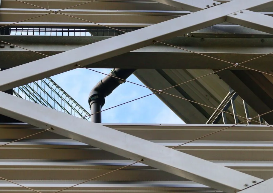
For containerized UF skids, the lift-and-set sequence is the first controlled lift of the project. Crane the pre-piped, 41'-6" container onto the cured foundation, level to ≤2 mm/m using a digital level, and torque the anchor bolts to the OEM specification — typically a calibrated torque-wrench value, not "snug." A containerized skid can be paired upstream with a GX Series rotary mechanical bar screen to protect the 200 µm pre-filter from gross debris and extend backwash intervals. The interconnecting pipework — feed, filtrate, backwash, CIP inlet, and drain — must each be sloped to allow full drain-down; stagnant water sitting in a depressurized module is the precursor to biological fouling within 48 hours.
Confirm instrumentation is in place and wired before any water flows: feed pressure transmitter, TMP differential transmitter (filtrate minus feed, or feed minus concentrate, per skid P&ID), filtrate turbidity meter, and flow meters on permeate and backwash lines. Electrical and control terminations should be performed by a qualified electrician against the IO list. The single most common commissioning-day mistake is energizing the CIP dosing pumps before the loop is filled; dry-running a centrifugal or positive-displacement chemical pump even briefly can destroy seals and invalidate the CIP commissioning step entirely.
Hydraulic Flushing and CIP Loop Commissioning
Hydraulic flushing removes welding debris, scale, and installation swarf from interconnecting pipework before membrane exposure. Step 1: flush all interconnecting pipework with clean water at service flow, with the isolation valves to the membrane modules kept closed. Step 2: fill the membrane modules slowly from the bottom up to displace air; vent the topmost air valves on each rack until a steady water stream appears with no sputtering. Air pockets trapped in a pressurized module will cause localized flux spikes and can crack the potting compound if the system is then pressurized against a trapped bubble.
Step 3: commission the CIP loop with clean water only — verify the dosing pump stroke, tank level switches, the heating element setpoint (typically 30–35°C for alkaline CIP, 25–30°C for acid CIP), and the return-line pH and temperature instrumentation. Step 4: run a full CIP water-only circulation to confirm valve sequencing, check for line leaks at every flange, and validate tank turnover. This is the dress rehearsal for the chemical CIP; any valve that fails to seat, any instrument that reads out of range, or any leak that shows up here will be a much larger problem once 200 L of heated NaOH is circulating through the same loop. The broader chronological pattern — flushing first, then integrity test, then CIP — is consistent with any 2026 lamella clarifier installation and commissioning protocol being executed on the same site.
Membrane Integrity Test: The Pressure-Decay Acceptance Gate
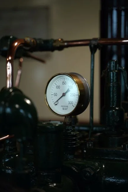
The pressure-decay test is the single most important handover step, and it must pass before any process water enters the rack. Procedure: isolate the module (or rack), pressurize the filtrate side with clean, oil-free compressed air to 0.2–0.3 bar per OEM specification, and hold the pressure for 5–10 minutes while logging the decay on a calibrated gauge or data logger. Pass criterion: pressure decay ≤ OEM-specified value — typically ≤0.05 bar over 5 minutes for a 0.01 µm PVDF hollow-fiber module. Any module exceeding the limit must be located with bubble-point probing (soap solution applied to the fiber ends while the module is pressurized) and the broken fiber repaired with the OEM-supplied resin kit, or the module replaced outright.
This test is non-negotiable because the entire value proposition of UF as RO pretreatment depends on it. The 0.01 µm pore size is what guarantees <2 SDI permeate to the downstream RO; a single broken fiber lets particulates bypass the membrane, the SDI creeps above 2, and the RO membranes start fouling on day one (WesTech, 2026). The 32–104°F / pH 1–10 operating envelope also constrains the integrity-test air supply — regulators must be oil- and particulate-free, and any chemical that later contacts the membrane during CIP must be pre-qualified against the same envelope to avoid accelerated fiber degradation.
The pressure-decay integrity test is a hold-and-measure procedure in which a UF module's filtrate side is pressurized with clean air to a specified setpoint and the pressure loss over a fixed dwell time is compared against an OEM-defined threshold, with any module exceeding the threshold failing the acceptance gate before process commissioning begins.
Performance Acceptance Run: Sign-Off Against a Parameter Table
The performance acceptance run verifies operational capability over 24 hours on actual feed water at design flow. The run is performed with backwash and CEB cycles executed on the programmed timer, and data logged at 1-minute intervals into the skid historian. The table below is the minimum parameter set a 2026 EPC engineer should be able to stamp at handover.
| Parameter | Design Value | Measured Value | Pass / Fail |
|---|---|---|---|
| Feed pressure | 1.5–3.0 bar (per OEM) | ___ bar | ☐ |
| Transmembrane pressure (TMP) | 0.3–1.0 bar at design flux | ___ bar | ☐ |
| Permeate flow | Design gpm per module (10–40 gpm range) | ___ gpm | ☐ |
| Recovery | 90–95% (surface water) | ___% | ☐ |
| Permeate SDI₁₅ | < 2 (RO pretreatment target) | ___ | ☐ |
| Permeate turbidity | ≤ 0.1 NTU | ___ NTU | ☐ |
| Design flux | 40–80 LMH (feed-water dependent) | ___ LMH | ☐ |
| CIP chemical concentration | Per OEM CIP recipe | ___ % | ☐ |
The design values above are anchored to the WesTech-class envelope for a 0.01 µm PVDF containerized skid: <2 SDI permeate, ≤0.1 NTU turbidity, and 90–95% recovery on typical surface water, with reject routed either to drain or to a downstream DAF for solids capture (WesTech, 2026). At the 7.5 MGD scale of a plant like Doyon JBER — 10,000+ sq ft of process building, 40,000 end users — a regulator or owner representative will ask to see this exact table, signed and dated, before issuing the substantial-completion certificate. If a 2026 filter press retrofit and upgrade guide is also in scope downstream of the UF reject, the TMP and turbidity values in this table set the baseline against which sludge dewatering performance is later evaluated.
Documentation, Training, and Handover
The handover dossier converts a working skid into an operable asset. Required contents: as-built drawings (not the construction-issue set, the red-lined final), the commissioning report including the signed acceptance table, calibration certificates for every instrument, individual membrane serial numbers with the OEM warranty registration, the CIP recipe library (alkaline concentration, acid concentration, temperature, dwell time, frequency), and the as-left PLC program archive on a dedicated USB. A useful 2026 procurement option is a remote-monitoring gateway — aligned with the broader 2026 smart water monitoring outlook for IoT-enabled UF plants — so the OEM can see TMP drift and CIP effectiveness in real time rather than waiting for a service call.
Operator training should cover startup, shutdown, backwash, CEB, CIP, integrity test, and emergency response to a high-TMP alarm, with each scenario walked through on the actual HMI. Adjacent equipment such as a JY series integrated water purification system or a HydropureWater multi-media filter upstream should be referenced in the training so operators understand the whole pretreatment train, not just the UF skid in isolation. A fully documented handover is what converts a 7-figure membrane asset from a liability into a 15–20-year operating asset.
Frequently Asked Questions
What is the typical pass criterion for a UF pressure-decay integrity test?
For 0.01 µm PVDF hollow-fiber modules, the standard pass criterion is a pressure decay of ≤0.05 bar over a 5-minute hold at 0.2–0.3 bar pressurization, though the OEM-specified value is always the contractual reference (WesTech, 2026).
What SDI should UF permeate deliver to a downstream RO system?
UF permeate should consistently deliver an SDI₁₅ below 2, which is the recognized RO pretreatment target and the headline value that justifies UF's position ahead of multimedia or cartridge filtration on a 2026 RO feed train (WesTech, 2026).