

What MBBR Sizing Actually Solves For
MBBR capacity and sizing collapses to three inputs you control: design flow Q in m³/d, influent BOD load in kg BOD/d (equal to Q × BOD_in), and a target effluent BOD or COD set by your discharge permit. The calculation must hand back two outputs — the gross tank volume in m³ that fits on the plot, and the effective working volume in m³ after subtracting the space taken by carriers and aeration pipework. The textile pilot at Universitat Politècnica de Catalunya ran an MBBR with one-day HRT, two aerobic chambers holding different carrier types separated by carrier-retaining grids, and delivered 82% COD removal with 73% TSS removal (UPC thesis, 2021). That operating point is the reference case used later in this guide. The key difference from CAS sizing: MBBR fixes biomass on carriers, so the design variable is biofilm surface area, not mixed liquor suspended solids concentration. You pick a carrier fill fraction and a specific surface area, and those two numbers fix how much biology the reactor can hold.
The Sizing Formula Chain, Step by Step
Each sizing calculation follows six sequential steps to ensure unit consistency. Do not skip the conversion line.
- BOD load L (kg/d) = Q (m³/d) × BOD_in (kg/m³). With BOD_in expressed in mg/L, divide by 1000 to get kg/m³. Example: 500 m³/d × 0.8 kg/m³ = 400 kg BOD/d.
- Required biofilm area A (m²) = L (g/d) ÷ BODv (g/m²·d). Industrial MBBRs typically run at 2–8 g BOD/m²·d; municipal plants run higher, around 5–15 g BOD/m²·d. The narrower industrial range reflects shock loads and toxic compounds common in textile and chemical effluent (per industry design guidance, 2024–2025).
- Effective reactor volume V_eff (m³) = A ÷ (carrier specific surface area × fill fraction). HDPE Kaldnes-type carriers sit in a 500–1200 m²/m³ specific surface area range, and fill fraction typically runs 20–67% of the reactor's free volume. Effective surface per m³ of reactor = carrier surface area × fill fraction.
- Gross volume V_gross (m³) = V_eff ÷ (1 − displacement factor). Displacement covers the volume taken by the carriers (roughly equal to the fill fraction), the air header piping, and the inlet distribution zone. Add a margin rather than treating displacement as a single fixed number.
- HRT check = V_eff ÷ Q. Industrial MBBR typically runs 4–24 h. The UPC textile pilot sat at the conservative end of that window at about 24 h, which is also why its MBBR-MBR hybrid hit 93% COD removal at 1-day HRT (UPC thesis, 2021).
- Oxygen demand check. Required air in Nm³/h is set by oxygen demand (BODv × A) divided by oxygen transfer efficiency at field conditions. The reference Sigma MBBR skid uses side channel blowers rated at 150 m³/h at 0.3 bar — a real-world blower benchmark at one specific design point, not a number to extrapolate to other flows (Sigma DAF Clarifiers, 2025).
Worked Example: Sizing an MBBR for a 500 m³/d Textile Effluent
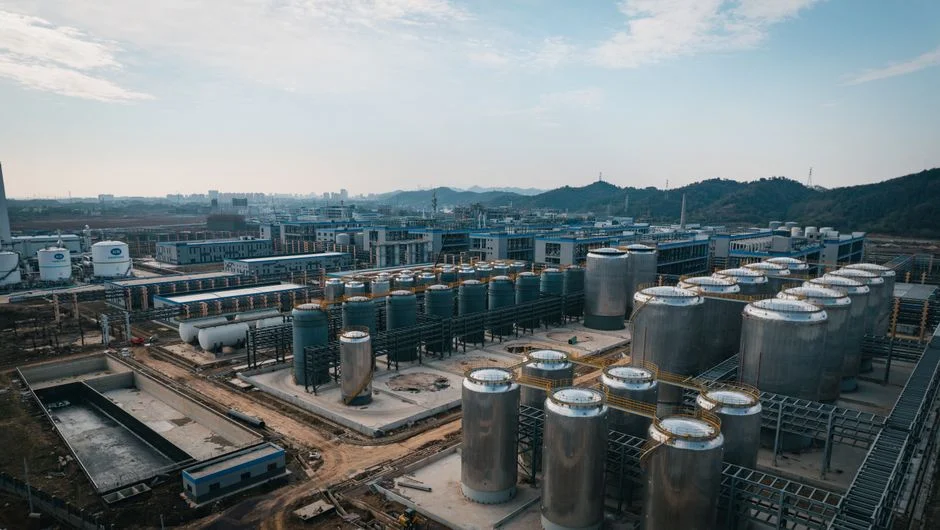
The numbers below are illustrative; they reproduce the S1 textile pilot conditions scaled to a typical plant flow so an engineer can repeat the math for any real influent.
| Parameter | Value | Source / basis |
|---|---|---|
| Design flow Q | 500 m³/d | Assumed plant flow |
| BOD_in | 800 mg/L = 0.8 kg/m³ | Textile influent, illustrative |
| BOD load L | 400 kg/d = 400,000 g/d | Q × BOD_in |
| BODv chosen | 5 g/m²·d (mid-range industrial) | Industrial design range 2–8 g/m²·d |
| Required biofilm area A | 80,000 m² | 400,000 g/d ÷ 5 g/m²·d |
| Carrier specific surface area | 800 m²/m³ | HDPE Kaldnes range 500–1200 m²/m³ |
| Fill fraction | 40% | Mid-range of 20–67% |
| Effective surface per m³ of reactor | 800 × 0.40 = 320 m²/m³ | Carrier surface × fill |
| V_eff | 80,000 ÷ 320 = 250 m³ | Working volume |
| V_gross (fill-only displacement) | 250 ÷ (1 − 0.40) ≈ 417 m³ | Add air-pipe / distribution allowance on top |
| HRT check | 250 ÷ 500 = 0.5 d = 12 h | Inside 4–24 h industrial window |
| Expected COD removal | ~82% | UPC textile pilot, 2021 |
| Expected TSS removal | ~73% | UPC textile pilot, 2021 |
Effluent from that 800 mg/L COD influent drops to roughly 144 mg/L at 82% removal — the pilot-scale figure, and bench numbers should be derated for full-scale design. The 12 h HRT sits comfortably inside the industrial 4–24 h range and lines up with the one-day HRT that the UPC pilot used (UPC thesis, 2021).
Design Parameters That Move the Answer
Specific process variables dictate reactor size and operational requirements.
| Design lever | Typical range | Effect on reactor size |
|---|---|---|
| Carrier fill fraction | 20–67% | Doubling fill roughly halves the required effective volume, up to the mixing limit where carriers start colliding. |
| Carrier specific surface area | 500–1200 m²/m³ | Higher surface area shrinks the reactor at the same BODv, but denser carriers cost more per m³ and mix less freely. |
| BOD volumetric loading (BODv) | 2–15 g/m²·d | Higher BODv shrinks the reactor, but pushes effluent quality down and raises oxygen demand. |
| HRT (industrial) | 4–24 h | Short HRT shrinks the tank, but risks washout of slow-growing nitrifiers and colour-removing biomass in textile flows. |
| DO target (aerobic) | 2–4 mg/L typical | Drives blower power, not tank volume. Below ~2 mg/L, BOD removal efficiency falls and the loading assumption no longer holds. |
| DO target (anoxic / anaerobic) | ≤0.5 mg/L typical | Sets the mixing-energy budget for anoxic or anaerobic chambers, not the tank size. |
| Temperature | 10–35 °C operating window | Biological rates (and therefore allowable BODv) drop as temperature drops, so a winter design needs derating. |
The two-stage aerobic configuration from the UPC pilot and the Sigma skid uses two aerobic chambers with different carrier types, connected by a channel fitted with carrier-retaining grids so each carrier stays in its own chamber. The first chamber runs at a higher BODv for carbon removal, the second runs at a lower BODv for polishing or nitrification, which gives better effluent stability than a single chamber of the same total volume. Downstream of the MBBR, the Sigma skid uses a honeycomb lamella clarifier at 80 mm clearance, 60° discharge angle, and 3.2 m²/m³ surface area — a smaller clarifier than CAS would need because the MBBR effluent carries lower TSS (Sigma DAF Clarifiers, 2025).
Pre-Treatment, Carrier Retention, and Other Sizing Killers
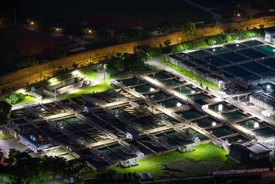
An MBBR system is only as effective as its upstream protection. If the upstream screen is too coarse, rags wrap around the carrier-retaining grids. If oil is not stripped, it coats the biofilm and the BODv assumption collapses. If pH drifts, the bacteria slow down and the effective reactor volume shrinks even though the tank did not. The Sigma skid states that the pollutant load typically receives primary treatment before entering the MBBR, and the connecting channel between chambers carries grids sized smaller than the smallest carrier dimension to keep each carrier type in its own chamber (Sigma DAF Clarifiers, 2025). Upstream of the MBBR, fine screening to around 3 mm aperture protects carriers from ragging, and a GX series rotary mechanical bar screen at the head of the works handles that step in most textile and food plants. Flow and load equalization upstream is what lets the engineer size the reactor for a sensible average load rather than a peak that doubles the volume. Outside roughly pH 6.5–8.5 and below about 10 °C, biological rates — and therefore the allowable BODv — fall off, so a sizing done on summer data is not a sizing done on winter data. For a deeper view of equalization and pH control on industrial flows, the textile wastewater treatment engineering guide covers the upstream envelope in more detail.
When to Step Up to an MBBR-MBR Hybrid
Hybrid systems are necessary when discharge consent sets a tight TSS limit, a colour limit that biofilm alone cannot break, or a water-reuse target that the secondary clarifier cannot reliably meet. In those cases, putting a membrane downstream of the MBBR changes the sizing logic: the MBBR upstream of the MBR can keep the same 1-day HRT as the standalone case, because the membrane handles the solids separation. The UPC pilot's hybrid hit 93% COD removal, 85% colour removal, and 99% TSS removal at 1-day HRT, and the same thesis reported 68.4% CAPEX saving against a standalone MBR at the same OPEX, with an 18% internal rate of return at industrial scale (UPC thesis, 2021). For engineers sizing a new train, the relevant MBR membrane bioreactor system downstream of the MBBR, paired with a DF series PVDF flat sheet membrane module for the solids-separation step, is the standard configuration. The comparable sizing question for hotel and food flows — where IFAS rather than pure MBBR is often the right call — is covered in the IFAS for hotel wastewater design guide.
Frequently Asked Questions
What is the basic formula for MBBR reactor volume?
The working formula is V_eff (m³) = BOD load (g/d) ÷ [carrier specific surface area (m²/m³) × fill fraction × BODv (g/m²·d)]. For a 500 m³/d textile plant at 800 mg/L BOD_in and 5 g/m²·d BODv, that gives V_eff of 250 m³ with 800 m²/m³ carriers at 40% fill, and a gross volume around 417 m³ before adding air-pipe and distribution allowances.
What BOD volumetric loading should I use for an industrial MBBR?
Industrial MBBR typically runs 2–8 g BOD/m²·d, lower than the 5–15 g/m²·d range used in municipal plants because industrial flows carry shock loads, toxic compounds, and temperature swings. The UPC textile pilot at 1-day HRT and 82% COD removal used a BODv near the lower end of that industrial window (UPC thesis, 2021).
Can an MBBR hit reuse standards on its own?
Not usually. A standalone MBBR with a downstream lamella clarifier delivers about 73% TSS removal and 82% COD removal in the textile pilot (UPC thesis, 2021) — fine for many discharge consents, but