
Why Biodiesel Wastewater Is Hard for Conventional Biological Treatment
Biodiesel plants generate an effluent that punishes conventional aerobic biology in four ways at once. Transesterification splits triglyceride feedstock into fatty acid methyl esters and a dense glycerin phase that lifts influent COD into the 5,000–30,000 mg/L range and pushes the BOD/COD ratio to 0.5–0.7, meaning the carbon is genuinely biodegradable but arrives in slugs tied to batch reactor discharge. Residual methanol from the reaction typically reaches 0.5–2% by volume in the aqueous phase, and methanol begins to inhibit Nitrosomonas above roughly 1% (10,000 mg/L) — a threshold many biodiesel equalization basins cross during a wash cycle. Free fatty acids from feedstock pretreatment and emulsified FOG from the degumming step add 200–3,000 mg/L of oil, which blinds diffusers, blankets biomass, and triggers chronic foaming. Acid and alkali cleaning steps swing pH between 2 and 12 across a single shift, which a continuous-flow activated sludge basin cannot buffer without massive equalization volume.
Diffused-air activated sludge and conventional SBRs cope badly with this combination. Nitrifiers, which double every 8–12 hours, wash out under FOG shocks that pull mixed liquor out with the foam. Methanol spikes shift the carbon metabolism toward heterotrophs and starve the nitrifying population. High-strength loading forces operators to hold DO above 2 mg/L to keep the heterotrophs alive, and the blowers that supply that DO typically account for 50–70% of a plant's aeration energy. The result is a process that is technically feasible but expensive to run, finicky to operate, and prone to permit excursions on total nitrogen when FOG and methanol spikes coincide.
How MABR Works: Counter-Diffusion Biofilm in a Single Tank
A membrane aerated biofilm reactor (MABR) inverts the geometry of conventional aeration. Oxygen-permeable hollow-fiber or flat-sheet membranes are submerged in the mixed liquor; air at near-atmospheric pressure is fed to the lumen side, and oxygen diffuses bubble-free through the membrane wall into a biofilm that grows on the wastewater side. Because the membrane is the oxygen source, the highest dissolved oxygen sits at the base of the biofilm, and the lowest sits at the biofilm–bulk interface. Substrate (COD, ammonia, methanol) diffuses in the opposite direction, from the bulk liquid inward. The two fluxes meet inside the biofilm rather than at its surface — this is counter-diffusion, and it is the structural feature that makes MABR tolerant of inhibitors.
The concentration gradients create a stratified biofilm. Nitrifiers, which are slow-growing and oxygen-hungry, colonize the oxygen-rich base of the biofilm where they are physically shielded from bulk-liquid inhibitors like methanol, FOG, and free fatty acids. Heterotrophs that oxidize glycerin and other COD occupy the middle of the biofilm, and the outer anoxic layer — together with the bulk liquid above — supports denitrifying bacteria that convert the nitrite and nitrate back to nitrogen gas. The result is simultaneous nitrification-denitrification (SND) in a single tank, replacing the separate anoxic and aerobic chambers of a conventional plant (Fluence, S3).
The energy numbers follow from the physics. Because air passes through the membrane passively at near-atmospheric pressure rather than being compressed into fine bubbles that mostly escape to the atmosphere, MABR cuts aeration energy by up to 90% and overall plant energy by as much as 50% versus a conventional activated sludge plant of comparable capacity (Fluence, S3). A small low-pressure blower handles module air supply, while existing coarse-bubble diffusers handle periodic bulk-liquid mixing (Fluence, S2).
MABR Process Design Parameters for Biodiesel Effluent

Design numbers for a biodiesel-fed MABR track the general MABR envelope, with the caveat that pre-treatment sets the upper bound of what the biofilm can absorb. The table below summarizes typical engineering ranges for a post-DAF stream entering a submerged MABR basin at 10–35 °C.
| Parameter | Typical design range | Notes |
|---|---|---|
| OLR (organic loading rate) | 0.3–1.2 kg COD/m³·d | Lower end for high-FOG streams; upper end for stable post-DAF effluent |
| HRT (hydraulic retention time) | 6–24 h | 12 h is a defensible midpoint for post-DAF biodiesel effluent |
| Membrane flux (O2) | Controlled by lumen pressure; periodic backwash every 1–4 weeks | Backwash interval shortens as FOG residual rises |
| Bulk-liquid DO | 0.2–0.8 mg/L (anoxic bulk, aerobic biofilm base) | Set by blower cycling, not aeration tank DO |
| Temperature | 10–35 °C | Nitrification rate halves below ~10 °C; methanol stripping needed above 30 °C |
| Influent COD (post-DAF) | 3,000–5,000 mg/L standalone; up to 8,000 mg/L with equalization + recycle | Raw transesterification wash water should be equalized |
| Influent FOG | <100 mg/L (DAF outlet target) | Residual FOG above ~150 mg/L risks biofilm blinding |
| Residual methanol | <200 mg/L entering MABR | Use stripping or equalization bleed upstream |
Expected removal performance, framed as typical rather than guaranteed, runs 80–95% COD, greater than 95% BOD, 60–85% total nitrogen (higher when methanol dosing is controlled to avoid nitrifier inhibition), and FOG residual below 30 mg/L after DAF pre-treatment. Documented municipal pilots anchor the upper bound: the Stanford CR2C pilot reported TN below 3 mg/L and TP below 0.3 mg/L, and the CENTA Spain yearlong test of an Aspiral S1 recorded TN of 4.1 mg/L and TP of 0.4 mg/L (Fluence, S3). High-strength biodiesel streams track these numbers when the upstream load is controlled — the membrane tolerates the carbon; the pre-treatment train tolerates the inhibitors. FOG and methanol pre-treatment is therefore not optional: a HydropureWater DAF system upstream to knock FOG below 100 mg/L, paired with a methanol stripper or large equalization basin, is the standard feed specification.
MABR vs SBR vs MBBR for Biodiesel Plants: Head-to-Head
The honest comparison for a 10–50 ML/d biodiesel plant is not "MABR wins" but "MABR wins on energy and footprint, and loses on track record and pre-treatment dependency." A project engineer defending a technology choice to a CFO needs both halves.
| Criterion | SBR | MBBR | MABR |
|---|---|---|---|
| Aeration energy vs conventional AS | Baseline (high) | ~20–30% lower than SBR | Up to 90% lower (Fluence, S3) |
| Footprint | Largest (batch volume + decant) | Intermediate | 40–60% smaller than SBR (Fluence, S3) |
| FOG tolerance | Poor — foaming, decant losses | Moderate — carriers can blind | Good (post-DAF) — biofilm shielded at base |
| Methanol tolerance | Poor — nitrifier washout above ~1% | Moderate — biofilm offers some protection | Good — counter-diffusion shields nitrifiers |
| Operator skill | Moderate (cycle tuning) | Low–moderate | Moderate (membrane integrity monitoring) |
| Retrofit difficulty | Major (new basin) | Moderate (carriers in existing basin) | Low (submerged modules in existing aerobic basin) |
| CAPEX order of magnitude | Low–moderate (concrete-dominant) | Moderate | Higher equipment cost; lower civil cost |
| Biodiesel track record | Extensive | Moderate (food oil, tallow) | Limited but growing |
SBR remains the conservative choice for a new-build biodiesel plant that wants a technology with two decades of industrial references, and the companion SBR for biodiesel wastewater design guide walks through that path in detail. MBBR is the middle ground: moving plastic carriers give biofilm robustness, but the process still needs conventional aeration and FOG can blind the carriers if DAF is undersized. The MBBR design guide covers sizing and cost for that route. MABR is the lowest-energy, smallest-footprint option with the best inhibitor tolerance, but the limited track record on 100% biodiesel streams means the pre-treatment train must be designed defensively.
Retrofit Economics: Adding MABR to an Existing Biodiesel Plant
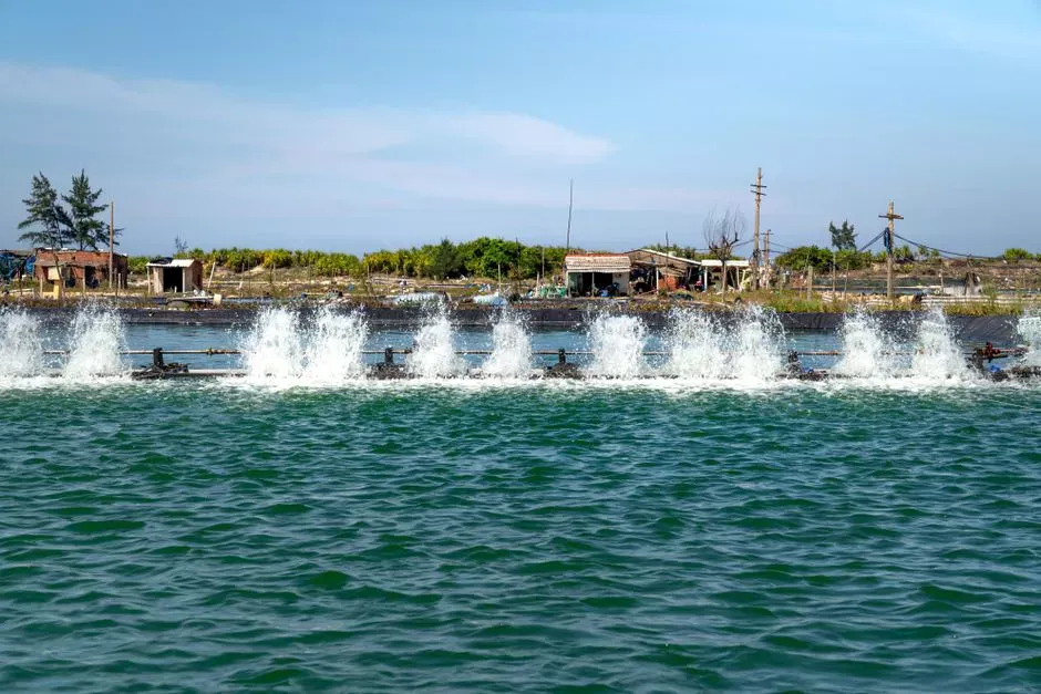
The strongest commercial case for MABR in an operating biodiesel plant is the submerged retrofit. Pre-engineered MABR modules are anchored to the floor of an existing aerobic basin and fed by a small low-pressure blower, leaving the existing coarse-bubble diffusers to handle bulk-liquid mixing. This installation approach is functionally analogous to the SUBRE retrofit paradigm documented for municipal plants (Fluence, S2): no new civil works, one basin taken offline at a time, and measurable effluent improvement within one to three weeks of start-up. Documented retrofit results report up to 30% reduction in overall plant energy use, with the largest gains on aeration (Fluence, S2). While those numbers come from municipal retrofits, the energy mechanism — replacing a compressed-air diffuser grid with passive membrane aeration — applies directly to a biodiesel basin.
Order-of-magnitude economics for a 10–50 ML/d retrofit land in a 2–4 year payback range when energy savings are monetized at typical industrial electricity tariffs, and shorter when carbon-credit revenue or renewable diesel margin uplift is included. Frame these as typical engineering estimates, not guarantees — actual paybacks hinge on local power cost, current blower loading, and influent temperature. New-build economics are more nuanced: MABR equipment costs more than SBR on a per-cubic-meter basis, but a 40–60% basin volume reduction (Fluence, S3) plus a smaller blower room can flip the total installed cost on a space-constrained site, especially where land or civil works dominate the capital bill. For plants wrestling with FOG versus oil-water separator performance, the MABR path is a downstream answer to a problem DAF alone cannot solve.
Integrating MABR into a Full Biodiesel Wastewater Train
The recommended flowsheet for a 5–50 ML/d biodiesel plant places MABR between robust pre-treatment and a polishing step. A complete train reads: equalization → pH correction and methanol stripper → DAF for FOG and suspended solids → MABR basin for carbon oxidation and simultaneous nitrification-denitrification → MBR or sand filter polishing → chlorine dioxide disinfection. Equalization absorbs the pH 2–12 swings from acid and alkali washing; DAF (a HydropureWater DAF system in the standard configuration) knocks FOG below 100 mg/L and suspended solids below the threshold that would blind the MABR biofilm; the MABR then runs at its design OLR of 0.3–1.2 kg COD/m³·d without inhibitor excursions. Effluent polishing through a HydropureWater MBR membrane bioreactor drops TSS below 5 mg/L and protects downstream RO if reuse is the target, and final chlorine dioxide disinfection handles fecal coliforms for the irrigation or boiler-feed reuse case. Sludge handling is lean: MABR biofilm produces far less waste activated sludge than a comparable CAS basin, and the wasted biofilm plus DAF skimmings route to a plate-and-frame filter press for dewatering to roughly 22–28% dry solids. Automation wraps the MABR basin in online DO, pH, and temperature probes driving a small PLC loop that modulates the low-pressure MABR blower and cycles the existing coarse-bubble mixers.
Frequently Asked Questions
Can MABR handle FOG spikes directly, or is DAF always required?
DAF is required. The MABR biofilm tolerates residual FOG below about 100–150 mg/L, but raw transesterification effluent at 200–3,000 mg/L FOG will blind the membrane and starve the biofilm of substrate. A well-sized DAF upstream is non-negotiable for biodiesel service.
What influent COD can MABR treat on its own?
Post-DAF biodiesel streams up to 3,000–5,000 mg/L COD are within standard MABR design range at 6–24 h HRT. Higher COD feeds need equalization and recycle to keep the OLR inside the 0.3–1.2 kg COD/m³·d window; otherwise the biofilm sloughs and effluent quality drops.
How long does a biofilm acclimate to biodiesel wastewater?
COD oxidation typically establishes within 2–4 weeks of continuous feed. Full nitrification capacity — including the counter-diffusion stratification that protects Nitrosomonas from methanol and FOG — takes 4–8 weeks. Operators should hold influent FOG below 100 mg/L and methanol below 200 mg/L during start-up.
Can MABR modules be retrofitted into an existing SBR basin?
Yes. The SBR can be converted to continuous-flow MABR with the modules in the aerobic phase, or kept cyclic with MABR handling the aerated fill segment. Either way, basin volume shrinks 40–60% versus the original SBR footprint once the MABR is at design OLR (Fluence, S3).
Is MABR effluent suitable for RO reuse in a biodiesel plant?
Usually not directly. MABR effluent carries low COD and TN but still contains suspended solids and biofilm particulates that foul RO membranes. An MBR or UF polishing step is needed upstream of RO; a HydropureWater MBR membrane bioreactor is the conventional pairing for reuse-grade effluent.