Why Hydrostatic Test Water Breaks Conventional MBR Sizing Assumptions
Hydrostatic test water arrives as one large batch per vessel or pipeline test — frequently 50–500 m³ every 2–8 weeks — separated by long idle periods when no feed enters the treatment system. Standard MBR design assumes a continuous diurnal flow with relatively stable COD, BOD, and ammonia loadings derived from sanitary or process wastewater. Applying those kinetics to a batch duty produces undersized equalization, starving biomass during idle weeks and shocking it during a single 4–8 hour drain event.
The influent itself is the second source of error. Test water typically carries COD of only 20–100 mg/L and low ammonia (often <5 mg/L as N) because the pipe or vessel has been filled with potable or demineralized water that picks up only incidental contamination. What it does carry is troublesome: TSS of 50–500 mg/L from rust, pipe scale, and welding slag; occasional oil (5–100 mg/L) from pump seal flush and hydrotest pump lubricants; dissolved iron of 2–20 mg/L from corrosion; and trace chromium, nickel, or zinc from carbon-steel corrosion products. The combination of low organics, high suspended solids, and intermittent dosing is the opposite of what biological kinetic equations were derived for.
F/M ratio collapses toward zero during idle weeks and spikes during the drain, so biomass must remain metabolically active without continuous substrate. A submerged PVDF module at 0.1 µm nominal pore handles the TSS polishing that sand filtration or clarifiers normally provide, but the upstream equalization basin must absorb the hydraulic shock first.
Step 1: Characterize the Test Water and Define the Design Batch
Before any sizing math, collect three datasets the project specification usually skips: test frequency (campaigns per year), largest single batch (m³), and total annual volume (m³/yr). Without the largest batch, the equalization basin will be undersized; without the frequency, the operator will discover too late that the membrane sits idle 80% of the time and fouls differently than a continuously fed unit.
Pull samples from at least three separate test events and analyze for COD, BOD₅, TSS, oil & grease, total iron, and any additive chemistry. Many hydrotest programs add nitrite-borate corrosion inhibitors, oxygen scavengers (sulfite or hydrazine derivatives), and biocide doses — each biodegradable in different degrees. Nitrite-borate blends are largely biodegradable and pass through MBR with minor adjustment; quaternary ammonia biocides are not, and should be removed by carbon adsorption before the bioreactor, not after.
Decide the reuse-versus-discharge endpoint before sizing any tank. Reuse requires MBR effluent at turbidity <1 NTU and TSS <1 mg/L; discharge to sewer typically needs only COD <50 mg/L and TSS <10 mg/L, which an MBR meets directly. Choosing the endpoint after the equipment list is locked in is the most common reason hydrotest water projects run 20–40% over budget (HydropureWater field data, 2025).
| Parameter | Typical Range | Why It Matters |
|---|---|---|
| Largest single batch | 50–500 m³ | Sets minimum equalization volume |
| Test frequency | 2–24 events/year | Determines idle-period biomass survival |
| COD | 20–100 mg/L | Drives aeration and F/M check |
| TSS | 50–500 mg/L | Sets pre-screen duty and membrane flux derating |
| Oil & grease | 5–100 mg/L | Triggers DAF or plate coalescer pre-treatment |
| Total iron | 2–20 mg/L | Major membrane foulant, controls flux derating |
| Additive chemistry | Nitrite-borate, sulfite, biocides | Determines if carbon adsorption is required upstream |
Step 2: Size the Equalization Basin (The Most Overlooked Step)
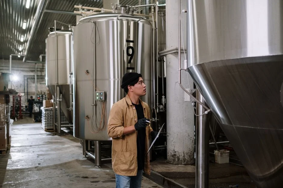
Equalization is the keystone decision. If the basin cannot absorb the largest batch plus the surge from simultaneous vessel tests, the bioreactor and membrane are exposed to raw hydrotest spikes that no amount of flux derating can absorb. Apply the 1.5× rule: equalization working volume equals 1.5× the largest single test batch, which provides headroom for fill, test dwell, drain, and treatment overlap. For a 200 m³ batch, that is 300 m³ minimum; add a 20% safety factor for unforeseen multi-vessel campaigns, giving 360 m³ (the value used in the worked example below).
Mixing and gentle aeration are mandatory, not optional. Iron hydroxide settles rapidly in quiescent zones, and any free oil resuspends as a sheen that carries straight to the membrane. Specify coarse-bubble diffusers at 2–5 m³ air per m³ water per hour — enough to keep solids in suspension and strip any sulfite-based oxygen scavenger, but well below the 10–20 m³/m³·h range used for biological aeration. A residence time of 12–36 hours in the equalization basin also lets settleable TSS drop out before the bioreactor sees it.
When any batch sample shows oil & grease above 50 mg/L, install an oil-water separation compartment or a coalescing plate pack at the inlet end of the basin. For very large single batches above 500 m³, a two-stage EQ basin with intermediate screening prevents the second stage from re-suspending material that already settled in the first. Protect the screens with a rotary mechanical bar screen at 3–6 mm opening to stop welding slag, pipe coupons, and protective wrap debris from reaching the bioreactor.
Step 3: Size the Bioreactor Tank and Aeration System
Bioreactor sizing for hydrotest water is driven by hydraulic retention during the batch, not by organic loading. Run MLSS at 6,000–9,000 mg/L — high enough to keep biomass viable through the long idle stretches between tests, low enough to limit membrane fouling when the batch finally drains. Design the basin for an HRT of 6–10 hours at the average daily flow that includes the batch, but recognize that during the actual 8–24 hour drain the effective HRT compresses to 4–6 hours because the basin is not refilling in parallel.
SRT of 30–60 days keeps the mixed liquor acclimated and ready when a batch arrives after a 4-week idle. Below 20 days, endogenous respiration consumes the active fraction; above 60 days, foam and pinpoint floc start fouling the membrane. F/M during an active batch sits at 0.02–0.05 kg BOD/kg MLSS·d — well below the 0.1–0.3 range of municipal design — and that is intentional, because the goal is polishing and iron oxidation, not carbonaceous BOD removal.
Actual oxygen demand is low because the BOD is low, but membrane scouring air must run continuously at 0.3–0.5 m³/m² membrane area per hour even when no feed is present, or the modules foul rapidly during idle periods. A common failure mode in intermittent MBR duty is turning the blowers off "to save power" between tests; this halves membrane life within 12 months (HydropureWater field data, 2024).
| Parameter | Design Value | Range Permitted | Reasoning |
|---|---|---|---|
| MLSS | 7,500 mg/L | 6,000–9,000 mg/L | Survives idle periods without excessive fouling |
| HRT (batch drain) | 6 h | 4–10 h | Absorbs shock load during drain |
| HRT (idle) | 24–48 h | — | Preserves biomass viability |
| SRT | 45 d | 30–60 d | Stable endogenous community |
| F/M (active batch) | 0.03 kg/kg·d | 0.02–0.05 | Intentionally low — polishing duty |
| Scour air (continuous) | 0.4 m³/m²·h | 0.3–0.5 | Must run during idle too |
Step 4: Size the Membrane Module and Flux Rate
For hydrotest water the membrane is a polishing and TSS-cut step, not a primary clarifier. Specify submerged PVDF flat-sheet or hollow-fiber modules at 0.1 µm nominal pore size; the material handles the pH excursions (6–9) and the occasional chlorination event during CIP, and the pore size delivers the <1 NTU turbidity a reuse loop requires. An integrated MBR membrane bioreactor system with factory-fitted modules shortens installation time on a plant utility skid where space is limited.
Apply a derated flux of 12–18 LMH versus the 15–25 LMH range typical of continuously fed industrial MBRs. The derate accounts for three intermittent-duty penalties: oil carryover that escapes upstream separation (even with a DAF pre-step), iron hydroxide that fouls faster than organic biomass, and the long idle periods that allow pore drainage and require restart transient handling. For a 200 m³ batch processed over 24 hours at 15 LMH, the required membrane area is 556 m² — see the worked example below for the math.
Calculate area as A = Q_peak / (flux × 24), where Q_peak is the average daily flow leaving the equalization basin during batch processing. Build in 15–20% redundancy by oversizing the cassette frame or specifying a spare rack, so that one cassette can be isolated for CIP while the rest of the train keeps producing. Run intermittent permeate operation — typically 10 minutes on, 2 minutes relax — which extends the cleaning interval substantially. With proper pre-treatment, CIP frequency of every 6–12 months is realistic; without it, every 2–3 months is the norm (HydropureWater field data, 2025). The modules themselves are DF series flat sheet membrane modules rated for this duty class.
| Design Parameter | Value | Notes |
|---|---|---|
| Membrane material | PVDF (submerged) | 0.1 µm nominal pore |
| Design flux (derated) | 12–18 LMH | vs. 15–25 LMH industrial norm |
| Operating cycle | 10 min on / 2 min relax | Extends CIP interval |
| Redundancy | 15–20% spare area | Spare cassette or oversized frame |
| CIP frequency (with pre-treatment) | 6–12 months | 2–3 months without it |
| Typical backwash flux | 30–40 LMH | Every 24–48 h during operation |
Step 5: Worked Sizing Example — 200 m³ Test Batch
Inputs: a pipe fabricator runs hydrostatic tests on four 200 m³ vessels per month (1,200 m³ cumulative), with design feed COD 60 mg/L, oil 30 mg/L, and total iron 5 mg/L. Reuse target applies because the next test cycle is two weeks later and freshwater cost is high at the site.
Equalization basin: 200 m³ × 1.5 × 1.2 = 360 m³ working volume, with coarse-bubble aeration at 3 m³ air/m³·h and a rotary bar screen at 5 mm opening on the inlet. A 50 m³ compartment at the inlet acts as an oil and grit catch when any batch exceeds 50 mg/L oil.
Bioreactor: the 200 m³ batch is drained from the EQ basin over 24 hours, giving Q = 8.3 m³/h. At a 6 h HRT during the drain, V_bio = 50 m³. Set MLSS at 7,500 mg/L and SRT at 45 days; scour air at 0.4 m³/m²·h on the membrane area calculated next.
Membrane area: at derated 15 LMH, A = 8.3 m³/h / (15 L/m²·h × 0.001) = 553 m². Round up to 600 m² by adding 8% redundancy, which fits four standard 150 m² cassettes in two skids.
Air demand: scour air only, since BOD is low: 0.4 × 600 = 240 m³/h continuous from dedicated blowers sized at 1.2× for altitude and fouling margin.
Reuse vs. Discharge: Choosing the Right Effluent Target
Reuse is attractive because MBR effluent from hydrotest water typically clears the bar without extra polishing — TSS <1 mg/L, turbidity <1 NTU, conductivity under 500 µS/cm for demin-source feed water, no free oil or foam. Discharge to a municipal sewer is simpler because the permit usually accepts COD <50 mg/L and TSS <10 mg/L, which an MBR meets directly. The decision is economic, not technical.
Use the 60% rule: if the next test cycle's fill-water demand equals or exceeds 60% of the volume the MBR can produce between batches, reuse pays back the incremental storage and polishing cost in 18–30 months through freshwater savings. Below 40%, discharge is the cheaper path. Between 40% and 60%, the answer depends on local water cost, sewer surcharge, and whether the site already has a treated-water storage tank.
If reuse is selected, add a 5 µm polishing cartridge filter ahead of the storage tank to protect the next test fill pump, and install a DAF system for oil and floatables removal upstream of the MBR whenever any batch exceeds 30 mg/L oil — the DAF is the cheaper insurance against membrane fouling. Sites with intermittent low-volume testing should compare this against the design rules covered in our notes on MBR sizing for factory white water and MBR for rinse wastewater when the test loop is downstream of a paint or coating process.
| Decision Factor | Reuse (next test fill) | Discharge to Sewer |
|---|---|---|
| MBR effluent target | TSS <1 mg/L, turbidity <1 NTU | COD <50 mg/L, TSS <10 mg/L |
| Additional equipment | Storage tank, 5 µm polish, level controls | Flow meter, pH/temp neutralization |
| Payback trigger | ≥60% of treated volume reused next cycle | Lower than 40% reuse ratio |
| Typical payback | 18–30 months | — |
| Best fit | High test frequency or costly freshwater | Low frequency, low freshwater cost |
Frequently Asked Questions
What is the minimum equalization basin size for a hydrostatic test MBR?
Size the basin at 1.5× the largest single test batch plus a 20% safety factor. For a 200 m³ batch, that is 360 m³. Going below this ratio is the most common cause of hydraulic shock and membrane fouling in intermittent-duty MBRs.
Why is the design flux for hydrotest water lower than industrial MBR norms?
The 12–18 LMH derate versus the 15–25 LMH industrial norm compensates for three intermittent-duty penalties: oil carryover that escapes pre-treatment, iron hydroxide that fouls faster than organic biomass, and the restart transients after long idle periods. A 15 LMH flux is a defensible midpoint for the worked example above.
Can MBR effluent from hydrotest water be reused directly for the next test?
Yes, for most demineralized or potable source feeds the MBR effluent meets TSS <1 mg/L and turbidity <1 NTU directly. Add a 5 µm polishing cartridge filter and a storage tank sized for at least 1.2× the next test batch, then verify conductivity and hardness against the test specification before each fill.
How do corrosion inhibitors and biocides in test water affect MBR operation?
Nitrite-borate corrosion inhibitors are largely biodegradable and pass through MBR with minor adjustment. Oxygen scavengers like sodium sulfite are oxidized in the equalization basin by gentle aeration. Quaternary ammonia and isothiazolone biocides are not biodegradable and must be removed by carbon adsorption ahead of the bioreactor to prevent biomass kill.
How long should membranes last on intermittent hydrotest water duty?
With proper equalization, a DAF pre-step for oil control, and continuous scour air at 0.3–0.5 m³/m²·h during idle periods, submerged PVDF membranes typically achieve 5–7 years of service with CIP every 6–12 months. Without those controls, membrane life often drops below 3 years and CIP intervals compress to 2–3 months. For a comparison on similar batch industrial waste streams, see our guide on MBR sizing for HF etch wastewater.