Why Deinking Reject Water Breaks a Residential RO Mental Model
Sizing an RO for deinking reject water starts with characterizing flow, COD (typically 3,000–8,000 mg/L), color, and silica, then applying a flux of 15–20 LMH and a recovery of 70–80% across a two-stage array. A DAF plus multi-media filter is required upstream to keep silt density index below 3, with permeate recycled to the mill and concentrate routed to ZLD or evaporation.
Deinking reject is the high-solids overflow from a flotation/clarifier loop in a recycled paper mill, typically 5–20% of the total mill water reuse load. It is not a clean feed stream, and it cannot be modeled with the recovery ratios used in a kitchen. The EPA WaterSense specification for point-of-use RO caps labeled residential units at 2.3 gallons of reject per gallon of treated water, while a typical point-of-use unit generates 5 gallons of reject per gallon treated and inefficient models hit 10:1 (per US EPA WaterSense, 2024). A mill designer reading that literature and applying it to a 20 m³/h reject stream will under-size the high-pressure pump, mis-classify the concentrate disposal cost, and burn through membranes in under 12 months.
Four industrial stressors make the residential mental model fail. First, residual fiber from the pulper fouls the lead-end spacer and collapses flux within days if not removed upstream. Second, colloidal ink and stickies (synthetic polymer fragments, hot-melt adhesives, and latex residues) cause irreversible plugging that no clean-in-place cycle fully reverses. Third, dissolved silica at 20–80 mg/L combined with calcium hardness produces a scaling envelope that caps system recovery around 80% even with antiscalant chemistry. Fourth, feed temperature of 45–60 °C from the pulper raises mass transfer but accelerates membrane compaction and shortens element life from the 5–7 years typical of cold brackish service to 3–5 years.
Step 1: Characterize Flow and Load Before Picking a Membrane
No RO vendor will quote a defensible number until the feed envelope is on paper. The first week of work is sampling, not sizing.
Pull 7-day composite samples and test for COD, BOD, TSS, color (Pt-Co), conductivity, silica, calcium, total hardness, temperature, and pH. For a recycled-paper deinking loop, expect COD in the 3,000–8,000 mg/L range, TSS 200–1,200 mg/L, color 1,500–5,000 Pt-Co units, and silica 20–80 mg/L (HydropureWater field data, 2026). Capture hot and cold samples separately: a 25 °C grab tells a different scaling story than a 55 °C composite pulled from the pulper overflow.
Size for peak, not average. Apply a 1.2 peaking factor to the maximum daily flow, because RO systems cannot ramp like a transfer pump — a membrane skid running at 90% of nameplate flux for 4 hours will foul faster than one running at 70% steady. Sample during a wash cycle spike when surfactant and ink loads are highest; the worst-case composite is the design basis, not the weekly average.
Define the target permeate quality before you pick a membrane. Reuse to the wire pit, dilution to a biological stage, or boiler feed each demand different rejection targets — a 95% salt rejection brackish element is fine for wire-pit reuse, but boiler feed at <10 µS/cm needs a two-pass RO or a polishing mixed-bed. Mixing these targets into "clean water" is where projects lose money.
| Parameter | Typical deinking reject | RO feed target | Test method |
|---|---|---|---|
| COD (mg/L) | 3,000–8,000 | < 200 (post-pretreatment) | Dichromate, 5220B |
| TSS (mg/L) | 200–1,200 | < 1 | 2540D |
| Color (Pt-Co) | 1,500–5,000 | < 50 (permeate) | 2120C |
| Silica (mg/L as SiO₂) | 20–80 | < 150 in concentrate | 4500-SiO₂ |
| Temperature (°C) | 45–60 | < 35 (cooled) | In-line probe |
| SDI₁₅ | — | < 3 | ASTM D4189 |
Step 2: Pick Flux, Recovery, and Array Geometry
Three coupled decisions determine membrane count, pump sizing, and concentrate volume: flux, recovery, and the stage ratio. Get any one of them wrong and the other two have to compensate.
Set flux at 15–20 LMH for deinking reject. Industrial brackish RO commonly runs 12–18 LMH on cleaner feeds; deinking sits at the upper end because the 45–60 °C feed temperature raises mass transfer roughly 2–3% per °C above 25 °C. Pushing past 20 LMH to chase membrane count savings compresses the lead-end spacer and accelerates fouling. Holding at 15 LMH or below buys CIP interval but raises element count and CAPEX.
Cap recovery at 70–80%. Beyond 80%, the silica saturation index and calcium sulfate scaling index both exceed acceptable limits even with polymeric antiscalant dosing; the concentrate stream then carries silica supersaturation that plates the tail elements within weeks. If the water balance demands 85%+ recovery, add a third stage or a concentrate recycle loop rather than pushing the two-stage array past its envelope.
Stage the array. For 75% recovery, use a 2:1 vessel ratio — for example, 8 vessels in the first stage and 4 in the second, each loaded with 6–7 elements. For higher recovery, add a third stage at 4:2:1 or install an inter-stage booster pump where concentrate pressure drops below 8 bar. Operating pressure for pretreated deinking water typically lands at 10–20 bar; concentrate recirculation pumps add 2–4 bar of boost.
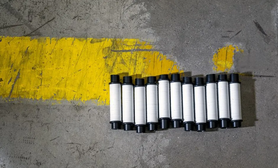
Calculate the membrane count. Divide required permeate flow by (flux × active membrane area per element, typically 35–40 m² for an 8-inch element). Round up to the next full vessel. For flows above 10 m³/h, specify 8-inch elements; for smaller pilots or sidestreams, 4-inch elements reduce footprint.
| Parameter | Recommended value | Reason |
|---|---|---|
| Flux | 15–20 LMH | Balances mass transfer and fouling at 45–60 °C |
| Recovery | 70–80% | Silica and CaSO₄ scaling cap above 80% |
| Array (75% recovery) | 2:1 (8:4 vessels) | Standard 2-stage brackish geometry |
| Array (85% recovery) | 3-stage with booster | Boosts concentrate pressure above 8 bar |
| Operating pressure | 10–20 bar | Brackish range on pretreated feed |
| Element size | 8-inch (flows > 10 m³/h) | Standard industrial footprint |
Step 3: Specify the Pretreatment Train That Protects the Membranes
An RO skid sized to the numbers above collapses within 90 days if the upstream train is not specified at the same time. The spiral-wound element manufacturer will void the warranty when SDI₁₅ exceeds 3 at the high-pressure pump suction — that single number drives the pretreatment envelope.
Lead with a dissolved air flotation unit for fiber, ink, and stickies. DAF removes over 90% of TSS in deinking loops (HydropureWater field data, 2026) and pulls a large fraction of the colloidal ink and stickies before they reach the media filter. Specify hydraulic surface loading at 15–25 m/h and an air-to-solids ratio of 0.03–0.06 by mass. The DAF effluent should land at TSS under 30 mg/L before the next stage.
Follow with a multi-media filter loaded with anthracite over sand over garnet. The graded media polishes TSS to under 2 mg/L and drops SDI₁₅ below the 3 threshold required for spiral-wound RO elements (per ASTM D4189). Backwash on differential pressure, typically at 0.7 bar.
Adjust pH to 6.5–7.2 with sulfuric acid dosing, and inject antiscalant (SHMP or a polymeric blend such as Genesys or Vitec) sized to the Langelier Saturation Index and silica saturation curve of the specific reject stream. A 5 µm cartridge filter as a guard ahead of the high-pressure pump is cheap insurance against a media upset — not a substitute for the DAF or MMF.
For component selection, an industrial DAF unit for fiber and ink removal paired with a multi-media filter for SDI reduction covers the two load-removal stages most projects skip or under-size.
Step 4: Concentrate Handling — Recycle, Evaporate, or Send to ZLD
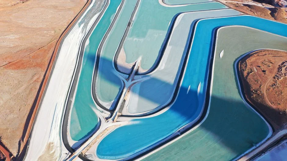
The 20–30% concentrate stream is the real cost driver in a 2026 RO project, not the membrane skid itself. At 75% recovery, 25% of the feed becomes a concentrate that carries most of the salts, silica, color, and residual organics — direct sewer discharge is blocked in most jurisdictions by effluent TDS or color limits.
Recycle the concentrate back to the pulper up to a conductivity ceiling of 3,000–5,000 µS/cm. Beyond that range, salt shock degrades the deinking chemistry (surfactant performance drops, calcium soap precipitation rises). When conductivity hits the ceiling, bleed the excess to a downstream volume-reduction step.
Route the bleed to a falling-film evaporator or a mechanical vapor recompression (MVR) unit when steam or electricity is cheap and water scarcity is moderate. Send it to a ZLD crystallizer when site water balance demands zero liquid discharge or when discharge fees exceed $8–$12 per m³. For a 5 m³/h bleed stream, evaporator plus crystallizer adds $1.2M–$2.5M to the 2026 project CAPEX, with steam or electricity as the dominant OPEX line (industry pricing, 2026). Energy for the evaporator alone runs 25–60 kWh per m³ of distillate, depending on MVR versus thermal-vapor compression.
Step 5: 2026 CAPEX, OPEX, and Side-by-Side Train Comparison
Translate the sizing work into a 2026 budget number the procurement team can act on. The line items below are equipment-only, excluding building, civil, and ZLD unless stated.
For a 20 m³/h deinking reject feed, a DAF + MMF + RO package lands at $280K–$520K in 2026 (industry equipment pricing, 2026). OPEX is dominated by three lines: membrane replacement on a 3–5 year cycle at $18K–$45K per swap, antiscalant and CIP chemicals at $0.04–$0.12 per m³ permeate, and energy at roughly 0.8–1.2 kWh/m³ permeate for the high-pressure pump and auxiliaries.
Three train configurations dominate the 2026 market. Option A is DAF → MMF → RO → evaporator, the workhorse for mills prioritizing water reuse with manageable salt discharge. Option B is DAF → MBR → RO, used when the discharge TDS or COD limit is tight enough to require biological polishing before the RO. Option C is DAF → MMF → RO → ZLD crystallizer, mandated when zero liquid discharge is required or when the site sits in a water-scarce basin with high discharge fees.
For a deeper read on the upstream sizing work behind options A and B, the 2026 DAF sizing guide for white water discharges and the MBR sizing guide for white water cover the hydraulic and load-removal envelopes in detail.
| Train | Water recovery | Salt rejection | CAPEX tier (20 m³/h) | OPEX tier | Best fit |
|---|---|---|---|---|---|
| A: DAF → MMF → RO → evaporator | 90–95% | 95–98% | $700K–$1.1M | Medium | Water reuse priority |
| B: DAF → MBR → RO | 70–75% | 95–98% | $450K–$780K | Low–medium | Tight discharge limits |
| C: DAF → MMF → RO → ZLD crystallizer | 95–99% | 99%+ | $1.6M–$2.9M | High | Zero liquid discharge mandated |
Decision rule: pick Option A when the mill's primary driver is water reuse and the discharge permit accepts evaporator condensate bleed. Pick Option B when biological polishing is required to meet discharge COD or color limits before the RO. Pick Option C only when ZLD is contractually mandated or when discharge fees exceed the energy cost of crystallization.
Frequently Asked Questions
What flux and recovery should I use for an RO on deinking reject?
Run 15–20 LMH flux at 70–80% recovery for pretreated deinking reject at 45–60 °C. Pushing past 80% recovery risks silica and calcium sulfate scaling even with antiscalant dosing (HydropureWater field data, 2026).
What SDI target protects spiral-wound RO membranes in a paper mill?
Hold SDI₁₅ below 3 at the high-pressure pump suction per ASTM D4189. A DAF plus multi-media filter train reliably delivers SDI₁₅ in the 1–2.5 range on deinking reject — verify with a 15-minute fouling index test, not just turbidity.
Should I put an MBR in front of the RO for a recycled-paper mill?
Use a DAF + MBR + RO train when the effluent permit demands <100 mg/L COD or <50 Pt-Co color after the RO, or when the deinking loop carries surfactant loads above 50 mg/L that a media filter cannot break down. The MBR sizing envelope is covered in the dedicated MBR sizing guide for white water.
How much does a 2026 deinking-reject RO package cost?
A 20 m³/h DAF + MMF + RO package runs $280K–$520K equipment-only in 2026 (industry pricing, 2026). Adding an evaporator pushes the project to $700K–$1.1M; a full ZLD crystallizer reaches $1.6M–$2.9M for the same feed flow.