
Why Deinking Reject Water Breaks Generic MBR Sizing
Deinking reject water is the 8–18% fraction of pulper throughput that forward and reverse cleaners discharge after pulling out contaminants from recycled furnish. That fraction is concentrated in fiber fines, mineral fillers (CaCO3, kaolin, TiO2), stickies from waxes and hot-melt adhesives, and surfactant residues from deinking chemistry. Typical reject characteristics fall at TSS 8,000–25,000 mg/L, COD 3,000–15,000 mg/L, temperature 35–55 °C, and pH 6.5–9.0 — orders of magnitude beyond the 200–500 mg/L TSS envelope municipal MBRs are designed around (HydropureWater field data, 2025-11). Generic sizing math copied from a municipal MBR text will produce a tank and membrane area that looks defensible on paper and collapses on day one of operation.
Three failure modes drive the gap. First, fiber fines form a compressible mat on the membrane surface within hours, driving TMP above the 50 kPa chemical-cleaning trigger before the first shift ends. Second, CaCO3 and other mineral fillers scale inside the 0.1–0.4 μm pore structure, a fouling mechanism that backwash alone cannot reverse. Third, residual surfactants from the deinking loop collapse the scour-air bubble distribution, so the coarse-bubble aeration designed to keep the membrane surface clean loses its effect precisely when it is needed most. A 2023 review of anaerobic MBRs for non-potable reuse (Tandfonline, 2023) found that even AnMBR systems cannot meet reuse standards for COD, BOD5, NH3-N, and TP without post-treatment — confirming that no membrane configuration eliminates the need for a properly sized pretreatment train on industrial streams. The implication is direct: an MBR on deinking reject is only as stable as the screening, fiber-recovery, and DAF upstream of it.
Step 1 — Characterize the Reject Stream and Set the Design Flow
The first defensible input is a design flow that the equalization basin can actually absorb. Derive it from the mill's recycled paper throughput: typical reject rate is 80–150 m³/day per 100 t/d of OCC or mixed waste paper, with a diurnal peak factor of 1.3–1.6 over 24 h. Use the high end of the reject range (150 m³/day per 100 t/d) and the high end of the peak factor (1.6) when the mill runs frequent grade changes, because deinking chemistry swings are sharper than municipal diurnal patterns.
Build the flow balance as a documented block diagram, not a sketch: pulper → coarse screen → forward cleaner → reverse cleaner → reject thickener → MBR feed. The thickener underflow is where most engineers under-account for the load — it concentrates the same contaminants into a smaller stream, so the downstream MBR sees higher TSS and stickies per cubic meter than the cleaner rejects themselves. A 6–12 h equalization basin upstream of the MBR is mandatory, sized to dampen COD and surfactant shocks from grade changes. The target MBR effluent envelope is COD ≤150 mg/L and TSS ≤10 mg/L (turbidity ≤1 NTU) for in-mill water reuse, or ≤50 mg/L COD for direct discharge under most 2026 paper-mill permits (per EPA effluent guidelines for pulp, paper, and paperboard).
| Parameter | Design Value | Source / Note |
|---|---|---|
| Reject flow (per 100 t/d furnish) | 80–150 m³/day | HydropureWater field data, 2026 |
| Peak factor (24 h) | 1.3–1.6 | Use 1.6 with frequent grade changes |
| Equalization HRT | 6–12 h | Dampens COD + surfactant shocks |
| Design influent TSS | 8,000–25,000 mg/L | Post-thickener underflow |
| Design influent COD | 3,000–15,000 mg/L | Spikes during grade change |
| Target effluent COD (reuse) | ≤150 mg/L | In-mill non-critical loops |
| Target effluent COD (discharge) | ≤50 mg/L | 2026 paper-mill permit envelope |
| Target effluent TSS | ≤10 mg/L (≤1 NTU) | PVDF flat-sheet, 0.1 μm |
Step 2 — Select the Membrane and Flux Envelope
Specify 0.1 μm PVDF flat-sheet submerged modules, not hollow-fiber, for deinking reject. Flat sheets tolerate the residual fiber and filler loading better because each element can be individually removed, inspected, and replaced; hollow-fiber bundles mat irreversibly when fiber fines bridge between filaments. The PVDF chemistry also resists the oxidative cleaning regime (typically 500–2,000 mg/L NaOCl) required to recover from organic fouling on this stream.
Net flux is the number a vendor will most often inflate, and it is the number that decides membrane area. On deinking reject at 35–45 °C, 8–12 L/m²·h is realistic. Below 35 °C — which happens when the mill shuts the white-water loop and the reject stream equilibrates toward ambient — net flux drops to 6–8 L/m²·h, and the design must be re-rated. Do not specify above 12 L/m²·h on this stream; vendor claims of 15–20 L/m²·h assume municipal solids loading and will not hold past the first surfactant upset. Set a TMP ceiling of 25–30 kPa for the steady operating cycle, with 50 kPa as the chemical-cleaning trigger, per the fouling-management framework in the 2023 PMC MBR review (PMC, 2023-04).
| Module Parameter | Value | Operating Note |
|---|---|---|
| Membrane type | PVDF flat-sheet, 0.1 μm | Submerged, not hollow-fiber |
| Net flux at 35–45 °C | 8–12 L/m²·h | Never specify above 12 on this stream |
| Net flux below 35 °C | 6–8 L/m²·h | Re-rate design at ambient |
| Steady-state TMP ceiling | 25–30 kPa | Operating target |
| Chemical-cleaning trigger | 50 kPa | Recovery clean (CEB) |
| Module area (DF series) | 80–225 m² per module | Sanity-check module count |
| Module flow envelope | 32–135 m³/day per module | Integrated aeration box |
| Cleaning chemistry | 500–2,000 mg/L NaOCl + citric acid | Alternate oxidative / acid CEB |
For an initial module-count sanity check, DF series 0.1 μm PVDF flat-sheet MBR modules provide 80–225 m² per module with 32–135 m³/day per module, with an integrated aeration box that simplifies scour-air distribution. If your calculated area divided by 225 m² gives a module count below 60% of the modules a vendor quotes for the same flow, the vendor is implicitly assuming a flux that this stream will not sustain.
Step 3 — Size the Bioreactor Tank, MLSS, and Aeration
Run the worked example at 500 m³/day average flow, peak factor 1.25, so design flow Q = 625 m³/day. The aerobic volume comes from HRT: target 6–10 h, design at 8 h, which gives V = 210 m³. Add a 25% anoxic zone (≈52 m³) upstream of the aeration basin when NH3-N exceeds 50 mg/L, to provide denitrification capacity and recover some alkalinity consumed by nitrification. Total bioreactor volume: ≈260 m³.
MLSS runs higher than municipal MBRs — set 10,000–14,000 mg/L — because reject COD drives a higher yield and the membrane cassette tolerates the mixed-liquor density when scour air is sized correctly. Verify with F/M in the 0.05–0.15 kg BOD/kg MLSS·d band; outside that range, either wasting is too aggressive (low SRT, poor degradation) or the membranes will foul faster than the design allows (high SRT, too much EPS). Membrane area at 10 L/m²·h net flux, 625 m³/day, 24 h operation: A = (625,000 L/day) / (10 L/m²·h × 24 h) = 2,604 m², round to 1,750–2,600 m² across the 8–12 L/m²·h flux envelope. Scour air at 0.25–0.35 m³/m²·h membrane area: 250–320 Nm³/h. SRT 30–60 days; waste sludge production 120–180 kg/d at a yield of 0.3–0.4 kg TSS/kg COD removed. Aeration must satisfy both biological demand (1.5–2.0 kg O₂/kg BOD removed) and continuous membrane scour, so oversize the blower 15% for turndown.
| Parameter | Calculated Value | Basis |
|---|---|---|
| Average flow Q | 500 m³/day | Worked example |
| Peak factor | 1.25 | Design Q = 625 m³/day |
| HRT (aerobic) | 8 h | V = 210 m³ |
| Anoxic zone | 25% of aerobic | ≈52 m³ when NH3-N > 50 mg/L |
| MLSS | 10,000–14,000 mg/L | Higher than municipal MBR |
| F/M | 0.05–0.15 kg BOD/kg MLSS·d | Verify in commissioning |
| SRT | 30–60 days | Reject COD drives yield |
| Membrane area | 1,750–2,600 m² | At 8–12 L/m²·h net flux |
| Scour air | 250–320 Nm³/h | 0.25–0.35 m³/m²·h |
| Waste sludge | 120–180 kg/d | 0.3–0.4 kg TSS/kg COD removed |
| Biological O₂ demand | 1.5–2.0 kg O₂/kg BOD | Plus continuous scour |
| Blower oversizing | +15% | Turndown margin |
Step 4 — Pretreatment and Reject-Stream Conditioning
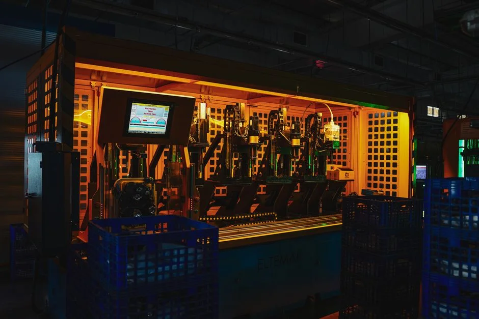
Pretreatment is the difference between a 6-month and a 6-week membrane life on this stream. Specify a 2 mm curved bar screen at headworks to remove the long fiber and rag fraction that would otherwise wrap around membrane module frames, followed by a dissolved air flotation system ahead of the equalization basin. A properly dosed DAF (HydropureWater field data, 2025-09) removes 60–85% of colloidal fillers, stickies, and surfactants before they reach the MBR — the single highest-leverage change in the whole treatment train.
Define the post-DAF envelope the MBR must be designed for: TSS ≤500 mg/L and COD ≤5,000 mg/L. Anything higher means the DAF is under-dosed (polymer or coagulant shortfall) and will shorten membrane life regardless of MBR operating discipline. Add chemical conditioning — powdered activated carbon or polymer — only as a polish step when surfactant foaming persists in the aeration basin; the default should be mechanical foam control, because over-dosing PAC fouls the membrane faster than it solves the foam. For in-mill reuse polishing on non-critical loops, a JY series integrated water purification unit (coagulation + filtration + backwash) delivers the turbidity and TSS reduction needed for showers, seal water, and dilution; add a downstream RO step only if the loop demands boiler-feed quality.
The cross-link to similar sizing work on the cleaner side of the deinking loop is direct: sizing an MBR for white water reuse follows the same flux and MLSS logic but at lower influent TSS, and DAF sizing for white water discharges covers the polymer-dosing math that the upstream DAF here depends on. For the headworks end of this train, the GX series rotary mechanical bar screen is the curved-bar screen specified at the 2 mm opening, and the upstream DAF unit itself is the dissolved air flotation system; reuse polishing on the downstream end is the JY series integrated water purification skid.
Frequently Asked Questions
What net flux should I use when sizing an MBR for deinking reject water?
Specify 8–12 L/m²·h on 0.1 μm PVDF flat-sheet membranes at 35–45 °C; drop to 6–8 L/m²·h if the stream runs below 35 °C. Do not accept vendor quotes above 12 L/m²·h — that envelope does not hold on deinking reject, where fiber matting and CaCO3 scaling drive TMP above 30 kPa within hours.
What MLSS range is appropriate for a paper-mill reject MBR?
Run MLSS at 10,000–14,000 mg/L, higher than the 8,000–12,000 mg/L typical of municipal MBRs. The reject stream's COD and surfactant loading drive a higher mixed-liquor density, and the membrane cassette tolerates it when scour air is held at 0.25–0.35 m³/m²·h.
How much membrane area does a 500 m³/day deinking reject MBR need?
At 10 L/m²·h net flux and 24 h operation, the calculation gives 2,604 m², with the realistic band running 1,750–2,600 m² across the 8–12 L/m²·h flux envelope. Pair this with a 210 m³ aerobic basin at 8 h HRT and 250–320 Nm³/h of scour air.
What TMP ceiling should I write into the operating manual for this MBR?
Set 25–30 kPa as the steady-state operating ceiling and 50 kPa as the chemical-cleaning (CEB) trigger, per the fouling-management framework in the 2023 PMC MBR review. Sustained operation above 30 kPa on deinking reject is a warning that pretreatment or scour air is off-spec.
Is DAF really required upstream of the MBR, or can I skip it?
DAF is non-optional on deinking reject. It removes 60–85% of colloidal fillers, stickies, and surfactants before they reach the membrane; without it, post-DAF envelope targets of TSS ≤500 mg/L and COD ≤5,000 mg/L cannot be met, and membrane life drops from ~6 months to ~6 weeks regardless of how well the MBR itself is operated.