
Why DAF Alone Does Not Treat Ammonia
A dissolved air flotation system does not oxidize ammonia-nitrogen. DAF is a physical separation process: saturated water is depressurized inside a flotation cell, releasing 10–100 µm micro-bubbles that attach to and lift free oil, FOG (fats, oils, and grease), tars, and suspended solids to the surface as a float layer, while clarified water exits below. Ammonia-nitrogen (NH3/NH4+) is fully soluble in the pH 6.5–8.5 window typical of most plant drains and passes through the DAF cell unchanged; recoveries for dissolved species are typically below 5% in jar tests on refinery wastewater (per the OFAT/DAF jar-tester study at doi.org/10.51415/10321/3182, 2025-11).
The practical consequence is that DAF belongs in the train as a protective clarifier around the downstream ammonia-removal step, not in place of it. Untreated FOG and tars coat nitrifying biofilm in MBBR or MBR stages, reduce oxygen transfer, and trigger sludge bulking — a failure pattern that typically shows up within 7–14 days of a feed upset when no clarification is fitted ahead of the bioreactor. By stripping the carriers upstream, DAF lets nitrification or breakpoint chlorination focus on the ammonia itself. The 2026 best-practice configuration for an ammonia drain is Acid–Coagulation–DAF (pre-treatment) at 5–7 bar saturation pressure, 20–50% recycle, and 10–100 µm micro-bubbles, followed by nitrification or breakpoint chlorination for discharge or cooling-tower reuse.
Ammonia Drain Characteristics That Drive DAF Sizing
Ammonia-bearing drains from four common source categories span a wide envelope, and each window drives different DAF parameters. Refinery sour-water stripper bottoms typically run 50–500 mg/L NH3-N; landfill leachate 200–2,000 mg/L; coker blowdown 100–1,000 mg/L; and fertilizer plant condensates 500–5,000 mg/L. Co-contaminants — the actual DAF load — usually sit at FOG 50–2,000 mg/L and TSS 200–1,500 mg/L, with phenols, sulfides, and tars adding to the floatable and colloidal fraction. Designing the DAF on the ammonia number alone is one of the most common sizing errors in 2026 retrofit work (HydropureWater field data, 2026).
Temperature affects air solubility because Henry's-law solubility of air in water drops from roughly 21 mg/L at 20 °C to about 14 mg/L at 60 °C. Many ammonia drains arrive at 40–70 °C straight from a stripper reflux condenser or hot leachate holding tank, which compresses the air-saturation margin and pushes designers toward the upper end of the 5–7 bar saturation range to compensate. Variability is the third driver: refinery slug loads from desalter upsets, batch landfill leachate deliveries, and coker decoking cycles can swing TSS by 3–5× inside an hour. An equalization basin sized at 6–12 hours of average flow, with mechanical mixing and a retention-loop pump, is the standard buffer ahead of any DAF on this kind of feed (HydropureWater field data, 2026).
Configuration A: Acid–Coagulation–DAF (Pre-Coagulation)
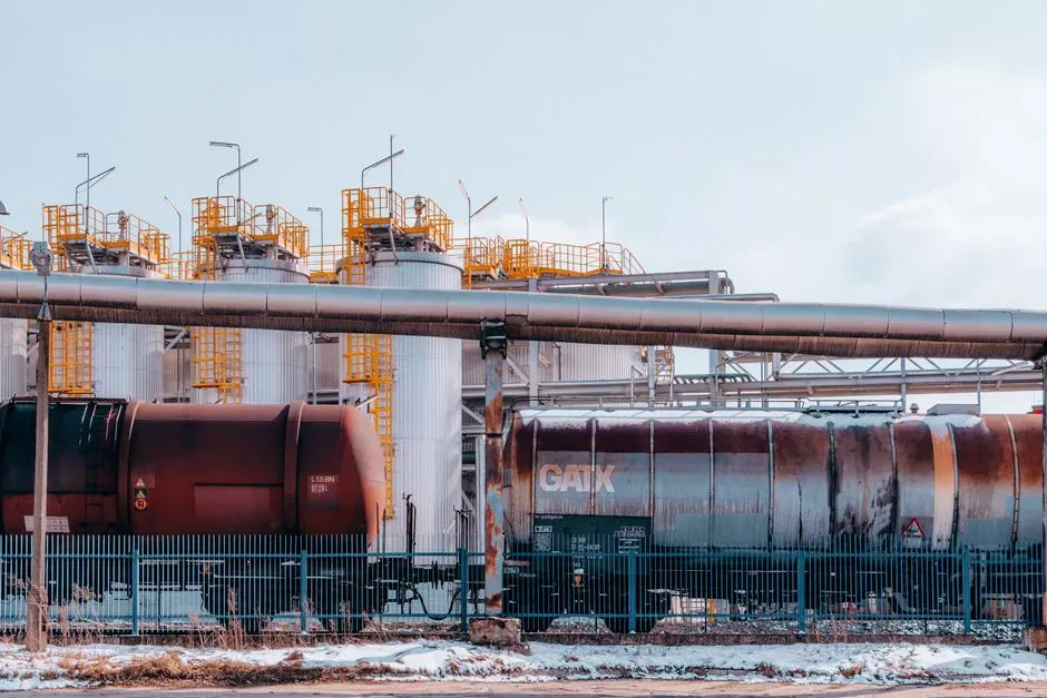
The preferred 2026 configuration for ammonia-bearing drain runs pH adjustment first, then coagulation, then DAF. Specifically: trim pH to 6.5–7.5 with sulfuric or hydrochloric acid (if sour-water stripper overhead is not already in that band), dose coagulant — typically polyaluminum chloride (PAC) 50–150 mg/L or liquid alum 100–200 mg/L — via an automatic chemical dosing system, then add anionic polyacrylamide flocculant at 1–5 mg/L, allow a 2–4 minute floc-blanket maturation, and send the stream to a dissolved air flotation system operating at 5–7 bar saturation and 20–50% recycle. AIRA-DAF works because destabilized FOG and colloidal solids are lifted to the surface before they reach the nitrification biofilm, where they would otherwise coat the carriers and cut nitrification rates.
Expected removals on a properly tuned Acid–Coagulation–DAF train are FOG 85–95%, TSS 80–95%, and oil & grease to <10 mg/L in the clarified effluent — comfortably below the 15 mg/L ceiling typically required for downstream MBR or MBBR feeds. Ammonia-N passes through at near-feed concentration, which is intentional: the DAF stage is the protector, and nitrification or breakpoint chlorination downstream handles the NH3/NH4+ load itself. The refinery pilot study cited above compared the same DAF hardware in two configurations and reported that the pre-coagulation option "yielded more recovery of water and oil, and hence this step was economically viable" (doi.org/10.51415/10321/3182, 2025-11), with the response-surface methodology run giving higher oil-and-water recovery than the one-factor-at-a-time baseline.
Configuration B: Acid–DAF–Coagulation (Post-Coagulation)
Configuration B utilizes pH adjustment, then DAF as the primary float, then coagulant/flocculant addition followed by a secondary clarifier or sand filter. It survives in 2026 mainly on hot streams — feeds above 55–60 °C where coagulant hydrolysis kinetics and floc strength degrade noticeably — and on sites where the float is sold or recovered as a separate product (tallow recovery at edible-oil plants, tars for off-site fuel blending). Smaller DAF footprint and 30–50% lower polymer dose are the headline benefits.
The trade-off is real. Without a coagulated floc blanket ahead of the cell, DAF carryover of fine suspended solids typically runs 1.5–3× higher than in Configuration A, and that carryover reaches the nitrification stage as a steady TSS load of 80–200 mg/L — enough to elevate MBR fouling rates and force more frequent chemical cleaning cycles. The same refinery pilot study noted that the post-treatment configuration "underperformed the pre-coagulation option on oil and water recovery" (doi.org/10.51415/10321/3182, 2025-11). For ammonia-bearing drain specifically, treat Configuration B as a fallback when temperature or float-recovery economics force the issue, not a default.
2026 DAF Parameter Table for Ammonia Streams
The following table provides a datasheet starting point for ammonia-bearing drains in 2026. Values are drawn from refinery and leachate operating data and the pilot study cited above; they are conservative bands, not single-point guarantees.
| Parameter | 2026 Best-Practice Band (Ammonia Streams) | Notes |
|---|---|---|
| Saturation pressure | 5–7 bar (standard); 4–5 bar for hot streams >55 °C | Drop to 4–5 bar when feed temperature is high to maintain air-solubility margin |
| Recycle ratio | 20–50% of forward flow | Push to the upper end for high-FOG or high-TSS envelopes |
| Hydraulic loading (cell surface) | 5–25 m/h | Lower end (<10 m/h) for emulsified FOG; upper end for low-TSS clarified streams |
| Micro-bubble size | 10–100 µm, target 40–80 µm | Smaller bubbles rise more slowly and attach to finer FOG droplets |
| Contact / flotation time | 3–5 minutes | Match skimmer surface overflow to float removal rate |
| Skimmer speed | 0.5–2 rpm | Slower for thicker float blankets to avoid water entrainment |
| Air-to-solids ratio (A/S) | 0.01–0.05 kg air / kg TSS | At typical ammonia-drain TSS (200–1,500 mg/L), 5–7 bar saturation supplies the needed air mass |
| Float solids content | 3–6% dry solids typical | Higher than gravity clarification float, easing downstream sludge handling |
Operating a dissolved air flotation system outside the saturation-pressure and recycle-ratio bands above is the most common cause of poor float quality on ammonia drains. If bubble counts drop below 8,000–10,000 bubbles per mL at the eye of the contact zone, suspect a clogged nozzle ring, a pressure drop across the saturation tank, or a recycle pump running below nameplate.
Routing Ammonia Drain After DAF: Reuse vs Discharge
The routing of DAF effluent depends on the required endpoint rather than the pre-treatment method. The four realistic 2026 paths are:
- Discharge to sewer: DAF effluent → equalization basin (6–12 h HRT) → integrated MBR membrane bioreactor system for nitrification/denitrification → UV or chlorination → outfall. Suits streams <500 mg/L NH3-N where the receiving POTW is sized to take the load.
- Closed-loop cooling-tower reuse: DAF effluent → breakpoint chlorination at a Cl:NH3-N mass ratio of approximately 8:1 to drive NH3 to N2 → secondary DAF polish for residual TSS → cooling-tower make-up. Suits refineries and coker plants looking to cut freshwater draw.
- Zero-liquid-discharge (ZLD): DAF effluent → reverse osmosis or evaporator/crystallizer. Energy-intensive; reserved for high-NH3 fertilizer condensates where discharge is not an option.
- Hybrid nitrification + breakpoint polish: DAF effluent → partial nitrification to ~20–30 mg/L NH3-N → breakpoint chlorination on the residual. Lower chemical cost than full breakpoint on raw DAF effluent.
For any reuse or discharge path involving a residual-disinfection step, a chlorine dioxide generator in the 50 g/h to 20,000 g/h capacity band is a complementary option to breakpoint chlorination, particularly where biofilm control in the cooling-tower loop is the priority. The pre-treatment framing of the DAF as a clarifier for downstream ammonia removal is consistent across all four paths (HydropureWater field data, 2026).
Frequently Asked Questions
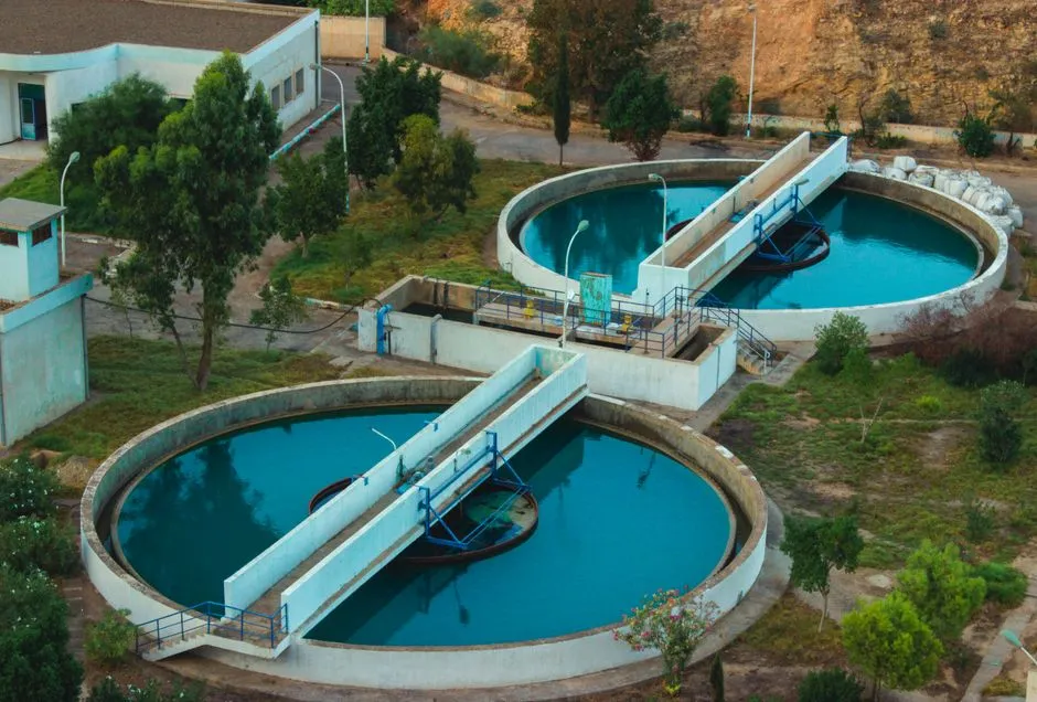
Does DAF remove ammonia from wastewater? No. DAF is a physical separation process that removes FOG, oil, tars, and suspended solids on 10–100 µm micro-bubbles; soluble ammonia-nitrogen (NH3/NH4+) passes through at near-feed concentration. Use DAF as a clarifier ahead of nitrification or breakpoint chlorination.
What DAF configuration is best for ammonia-bearing drain in 2026? Acid–Coagulation–DAF (pre-coagulation) is the 2026 default — pH 6.5–7.5, PAC 50–150 mg/L, anionic polyacrylamide 1–5 mg/L, then DAF at 5–7 bar saturation and 20–50% recycle. The pilot study at doi.org/10.51415/10321/3182 (2025-11) showed higher oil-and-water recovery for this order versus post-coagulation.
What saturation pressure and recycle ratio should I use for hot ammonia drain (50–70 °C)? Drop saturation pressure to 4–5