What Is Acid Mine Drainage and Why Standard Lime Treatment Falls Short
Acid mine drainage is a strongly acidic effluent with elevated concentrations of dissolved metals, metalloids, and sulfate, generated when sulfide-bearing rock is exposed to oxygen and water during and after mining (per a 2023 review in ScienceDirect, S3). Typical pH runs from 2 to 4, with iron, manganese, aluminum, and arsenic commonly exceeding 50 mg/L individually and sulfate often above 2,000 mg/L. Conventional treatment doses Ca(OH)2 to raise pH and precipitate metal hydroxides, but the resulting low-density sludge (LDS) settles as a gelatinous mass at roughly 2–5% solids. This low underflow density is the core pain point: thickener footprint, lime consumption, and ultimate disposal tonnage all scale with the volume of water locked into the sludge, not with the mass of metal removed. The BLM Technical Note 409 (April 2003, S5) framed this trade-off by contrasting passive sulfate-reducing systems with active neutralization-based HDS plants; the HDS concept was developed specifically to compress that sludge volume into a denser, more dewaterable cake without sacrificing treated-water quality.
Core Chemistry: How Neutralizers React with AMD
The dominant neutralization reaction is H2SO4 + Ca(OH)2 → CaSO4 + 2H2O, with the sulfate either leaving as gypsum or staying in solution depending on calcium and ionic strength. Generic metal precipitation follows Mn+ + nOH- → M(OH)n, and the practical pH at which each metal drops out is governed by its Ksp and oxidation state. The Horobetsu HDS study (S1) benchmarked three neutralizer options for the same synthetic AMD: Ca(OH)2 alone, a two-step CaCO3-then-Ca(OH)2 scheme, and MgO. Each carries different trade-offs: Ca(OH)2 alone has the fastest dissolution and tightest pH control but the highest unit cost per ton of acidity neutralized; the two-step CaCO3/Ca(OH)2 sequence leverages cheaper carbonate for bulk pH lift to roughly 5–6 and finishes with hydroxide for polishing, but adds a stage to the P&ID; MgO raises sludge density significantly, but its lower solubility forces longer residence time and tighter pH control to avoid local hot spots. Aeration in the reactor is required to oxidize Fe(II) to Fe(III), which precipitates as ferric hydroxide (Fe(OH)3) within the working pH window of 4–5, the first and largest metals removal step on the staged curve.
The HDS Recycle Loop: Why Seed Solids Change the Outcome

High-density sludge (HDS) utilizes a seed bed of previously precipitated metal-hydroxide solids held in the reactor as nucleation sites to improve sludge density. New metal hydroxide precipitates onto existing seed particles rather than nucleating fresh colloidal flocs, which drives the underflow toward 15–25% solids (a typical HDS operating range), versus the 2–5% baseline of conventional LDS. The recycle loop runs as a closed sequence:
- Raw AMD enters mix/equalization for flow and load dampening.
- Equalized feed enters the reactor, which already holds the seed bed at the target pH stage.
- Neutralizer is dosed under PLC control; online pH and ORP hold the working setpoint.
- Overflow from the reactor flows to a clarifier or thickener, where the seed solids settle.
- Underflow splits: a fraction is recirculated to the reactor to maintain seed inventory, the remainder is bled to sludge handling.
- Clarified effluent advances to polishing (typically metals/arsenic polishing, sometimes sulfate reduction or RO for closed-loop reuse).
The same treated water quality is achieved, but the bleed stream is a much smaller, denser volume—typically a fraction of the LDS baseline—which reduces thickener area, lime make-up, and ultimate disposal mass. The recycle separation is the job of the high-efficiency lamella clarifier for the HDS underflow separation, where the inclined-plate geometry recovers dense underflow at high solids content before the bleed stream moves downstream to dewatering.
Stage-by-Stage pH Windows and Metals Removal
Metals drop out in a predictable sequence set by their solubility products and oxidation state. The table below consolidates the working pH window, the dominant chemistry, and the practical control handle for each stage. It serves as the reference an engineer should pin to the control room wall before commissioning.
| Stage | pH window | Target species | Dominant reaction / mechanism | Key control handle |
|---|---|---|---|---|
| 1. Iron removal | 4.0–5.0 | Fe(III), Al(III) | Fe3+ + 3OH- → Fe(OH)3; Al3+ + 3OH- → Al(OH)3 | Aeration rate + ORP (must oxidize Fe(II) → Fe(III)) |
| 2. Manganese removal | 6.0–7.0 (in practice often >8) | Mn(II) | Mn2+ + 2OH- → Mn(OH)2; requires strong oxidation to Mn(III)/Mn(IV) oxyhydroxide | Stronger aeration + higher pH setpoint; hardest stage to meet |
| 3. Heavy metals & arsenic polishing | 7.0+ | Cu, Zn, Ni, Pb, Cd, As(III) and As(V) | Metal hydroxides + adsorption of As onto the recycled sludge surface | Final pH trim + sludge recycle ratio to maintain adsorption surface area |
The Horobetsu study (S1) confirmed that at pH 7, both As(III) and As(V) drop below the Japanese regulated environmental effluent standard via adsorption onto the sludge surface, rather than as a discrete hydroxide precipitate. Manganese is the practical exception: it stays soluble at low pH and demands both stronger oxidation and a setpoint above 8 in real operating plants. Sulfate is not removed by HDS neutralization; it passes through to the clarified effluent and must be addressed downstream by sulfate-reducing bioreactors, nanofiltration, or reverse osmosis if the discharge limit requires it.
Reactor and Clarifier Design Parameters
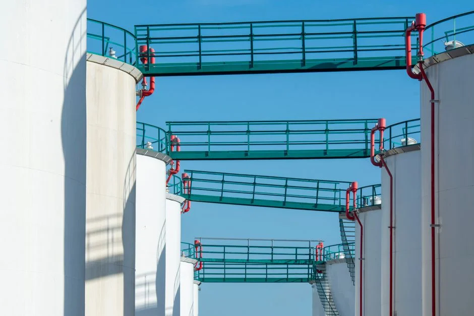
Hydraulic residence time for an HDS reactor is typically tens of minutes per stage. The staged neutralization logic—bulk pH lift in early stages and polishing in later ones—is the framework the Horobetsu study (S1) used to compare Ca(OH)2, CaCO3/Ca(OH)2, and MgO on the same AMD feed. The most important operating handle is the underflow recycle ratio: the fraction of clarifier underflow returned to the reactor to seed fresh precipitation versus bled to sludge handling. Raising the recycle ratio grows the seed bed inventory, which improves metals drop-out and arsenic adsorption but can push the clarifier toward hydraulic overload and starve the bleed stream of solids for dewatering; lowering it thins the seed bed, causing sludge density to drift down and metals removal to deteriorate. Online instrumentation makes this controllable: pH probes on every stage, an ORP probe on the oxidation step to confirm Fe(II) oxidation, and turbidity on the clarifier overflow to catch seed-particle carryover. Neutralizer feed is managed by a PLC-controlled chemical dosing system for the lime or MgO feed, which trims the pump stroke based on the pH signal to keep each stage inside its working window.
Sludge Handling: From Underflow to Disposal-Ready Cake
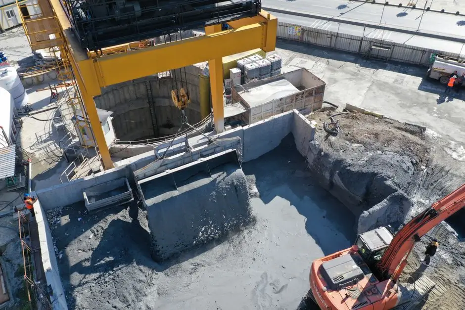
The dewaterability of the underflow determines whether HDS meets its volume-reduction goals. The Sustainability study (S4) evaluated HDS from AMD neutralization against several global waste-classification systems and classified it as a hazardous-status waste under selected frameworks—meaning the cake that leaves the filter press is a regulated material, not a benign byproduct. The dewatering chain is conventional: thickened underflow from the clarifier feeds a plate and frame filter press for HDS cake dewatering, which compresses the bleed stream into a filter cake in the typical 30–40% solids range. Residual management is jurisdiction-specific: an arsenic-laden cake that passes a TCLP limit in one region may still require secure landfill or chemical stabilization in another, so the engineer must cross-check local discharge and waste rules before specifying the disposal route. For sites targeting zero liquid discharge, the clarified effluent is routed to downstream sulfate polishing with reverse osmosis for closed-loop reuse, and any residual metals or organics that escape HDS can be addressed with advanced oxidation polishing for residual metals or organics after HDS.
Frequently Asked Questions
Why does HDS produce less sludge than conventional lime treatment?
Because the reactor holds a seed bed of previously precipitated metal hydroxides, new precipitates coat existing particles instead of forming fresh colloidal flocs. This allows the underflow to reach a typical 15–25% solids range versus 2–5% for LDS, reducing the bleed volume to disposal (per S1 framework).
What pH is required to remove arsenic in an HDS reactor?
At pH 7, both As(III) and As(V) drop below the Japanese regulated environmental effluent standard by adsorption onto the recycled sludge surface, not as a discrete hydroxide precipitate (per S1, Horobetsu study).
Does HDS remove sulfate from AMD?
No. Sulfate passes through the neutralization stage in the clarified effluent and must be handled by a downstream sulfate-reducing bioreactor, nanofiltration, or reverse osmosis if the discharge limit requires it.
Is HDS sludge classified as hazardous waste?
Under several global waste-classification systems evaluated in the Sustainability study (S4), HDS from AMD neutralization is classified as a hazardous-status waste; therefore, the dewatered cake is a regulated material and disposal routing must be checked against local rules.
Which neutralizer gives the densest sludge: Ca(OH)2, CaCO3, or MgO?
MgO produced the densest sludge in the Horobetsu HDS study (S1), but its lower solubility forces longer residence time and tighter pH control. Ca(OH)2 alone is the fastest-dissolving option, and the two-step CaCO3/Ca(OH)2 scheme sits between them regarding cost and density.