Wafer Fab HF Wastewater Treatment: 2025 Hybrid System Design with 99% Fluoride Removal & ZLD Cost Breakdown
Wafer fab HF wastewater treatment requires specialized systems to remove fluoride (>50 ppm typical), silica, and biological fouling while meeting strict discharge limits (e.g., 10 ppm fluoride). Modern hybrid systems—combining precipitation, nanofiltration (NF), and electrodialysis reversal (EDR)—achieve 99%+ fluoride removal and enable zero liquid discharge (ZLD). For example, a 150 m³/hour EDR system (Veolia, 2016) reduced fluoride to <1 ppm while reclaiming 85% of scrubber wastewater. Key challenges include variable influent quality (pH 3–5) and membrane fouling, addressed through automated chemical dosing and pre-filtration.Why HF Wastewater Treatment is a Critical Challenge for Wafer Fabs
Semiconductor fabs consume 2–4 million gallons of water per day, with HF wastewater originating primarily from wafer cleaning and etching processes (Chip Fab Wastewater Management article). Strict global fluoride discharge limits, such as 10 ppm in the US/EU, 15 ppm in China (GB 8978-2024), and 8 ppm in Singapore, mean that non-compliance carries significant financial penalties and can lead to production halts (Microelectronics Wastewater Discharge Standards 2025). For instance, a 300mm fab in Singapore faced $2.1 million in penalties for repeated fluoride exceedances, illustrating the severe consequences of inadequate treatment (hypothetical scenario based on Veolia case study). Beyond regulatory compliance, operational constraints further complicate HF wastewater management. Conventional calcium fluoride (CaF₂) precipitation systems often demand a substantial footprint, typically 3–5 times larger than advanced membrane-based solutions (Veolia EDR vs. sedimentation). This presents a significant challenge for fabs operating in space-constrained urban environments. increasing water scarcity in key semiconductor manufacturing regions, such as Taiwan and Arizona, mandates that fabs reclaim 70–90% of their wastewater to secure operational permits and ensure long-term sustainability (Chip Fab Wastewater Management article). Implementing zero liquid discharge (ZLD) solutions is becoming a strategic imperative to mitigate these risks and enhance water security.HF Wastewater Characteristics: What Your Treatment System Must Handle
| Parameter | Typical Influent Range (HF Wastewater) | Impact on Treatment |
|---|---|---|
| Fluoride (F⁻) | 50 – 500 ppm | Primary target for removal to meet discharge limits. |
| Silica (SiO₂) | 100 – 300 ppm | Causes scaling on membranes and precipitation systems. |
| pH | 3 – 5 (HF), 1 – 2 (BOE) | Requires neutralization for precipitation and membrane protection. |
| Total Suspended Solids (TSS) | 50 – 200 mg/L | Contributes to sludge volume, can foul membranes. |
| Temperature | 20 – 40°C | Affects reaction rates and membrane performance. |
| Flow Variability | ±30% | Requires equalization for stable operation. |
For more details on pH adjustment systems, refer to our guide on pH adjustment system engineering specs.
Treatment Technologies Compared: Removal Efficiencies, Footprint, and Limitations
Modern HF wastewater treatment systems leverage diverse technologies, each with distinct removal efficiencies, footprint requirements, and operational limitations. Calcium fluoride (CaF₂) precipitation is a well-established method, achieving 90–95% fluoride removal, but it generates substantial volumes of hazardous sludge, incurring disposal costs typically ranging from $200–$500 per ton in China (Industrial Wastewater case study). Nanofiltration (NF) systems offer superior fluoride removal, typically 95–99%, but necessitate rigorous pre-filtration to prevent silica scaling and membrane fouling (ScienceDirect FO-NF hybrid study). Electrodialysis Reversal (EDR) stands out with 98–99.5% fluoride removal, demonstrating higher tolerance for silica concentrations than NF, but it is an energy-intensive process with power consumption typically between 0.5–1.2 kWh/m³. Forward Osmosis (FO) provides excellent fluoride removal, often exceeding 99%, and exhibits low fouling tendencies due to its osmotic driving force, though it requires a robust draw solution recovery system, often integrated into a hybrid FO-NF configuration (ScienceDirect FO-NF hybrid study). Hybrid systems, such as precipitation followed by NF or EDR combined with ion exchange, represent the most advanced approach for achieving zero liquid discharge (ZLD), as demonstrated by Veolia's EDR + cartridge filters case study, which achieved high recovery rates for scrubber wastewater.| Technology | Fluoride Removal Efficiency | Typical Footprint (Relative) | Key Advantages | Key Limitations |
|---|---|---|---|---|
| CaF₂ Precipitation | 90 – 95% | Large (3-5x membrane) | Lower CAPEX, robust for high F⁻ | High sludge generation, residual F⁻ >10 ppm, large footprint |
| Nanofiltration (NF) | 95 – 99% | Medium | High F⁻ removal, water recovery | Requires robust pre-treatment (silica), fouling potential |
| Electrodialysis Reversal (EDR) | 98 – 99.5% | Medium | High F⁻ removal, tolerant to moderate silica, ZLD potential | Energy-intensive (0.5-1.2 kWh/m³), higher CAPEX |
| Forward Osmosis (FO) | 99%+ | Medium | Very low fouling, high F⁻ removal, high recovery | Requires draw solution recovery, complex integration |
| Hybrid Systems (e.g., Ppt + NF/EDR + IX) | 99%+ (ZLD capable) | Variable (optimized) | Maximized F⁻ removal, ZLD, high water recovery | Highest CAPEX/OPEX, complex operation |
For chemical dosing strategies to optimize precipitation, see our guide on how a flocculant dosing unit works.
Hybrid System Design: Step-by-Step Process Flow for 99% Fluoride Removal
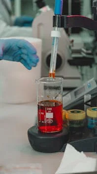
- Step 1: Equalization Tank A well-designed equalization tank is crucial to dampen the significant flow and quality fluctuations inherent in fab wastewater, typically sized for 2–4 hours of retention time. Effective mixing, often achieved with a velocity of 0.3–0.5 m/s, is essential to prevent solids settling and maintain homogeneity.
- Step 2: pH Adjustment The influent pH, typically 3–5, must be precisely adjusted to a target range of 6.5–7.5 to optimize the solubility of calcium fluoride and prevent membrane damage. This is accomplished using an automatic chemical dosing system for Ca(OH)₂ or NaOH, with typical dosing rates of 0.5–2 kg/m³ for influent fluoride concentrations around 50 ppm.
- Step 3: Precipitation Reactor Following pH adjustment, the wastewater enters a precipitation reactor with a retention time of 30–60 minutes. Here, calcium salts react with fluoride to form insoluble CaF₂, and a flocculant, such as anionic polyacrylamide (PAM) at 1–5 ppm, is dosed to promote the aggregation of fine precipitates into larger, settleable flocs.
- Step 4: Solids Separation Solid-liquid separation is critical to remove the formed calcium fluoride sludge. This is commonly achieved using a lamella clarifier, designed with a surface loading rate of 10–20 m/h, or a Dissolved Air Flotation (DAF) system, which operates at 5–10 m/h, particularly effective for lighter flocs. For high-efficiency sedimentation, HydropureWater offers high-efficiency sedimentation tanks.
- Step 5: NF or EDR Membrane System The clarified effluent then proceeds to a membrane system for advanced fluoride removal. Nanofiltration (NF), often using membranes like NF270 for 95% rejection, or Electrodialysis Reversal (EDR) with 0.2–0.5 mm spacers, can achieve 95–99.5% fluoride removal, depending on the desired effluent quality.
- Step 6: Post-treatment for ZLD For zero liquid discharge (ZLD) implementation, post-treatment further purifies the membrane permeate. This typically involves ion exchange or Reverse Osmosis (RO) systems, capable of achieving recovery rates of 85–95% for RO and 90–98% for ion exchange, ensuring high-quality reclaimed water suitable for reuse within the fab.
Learn more about pressure flotation systems for effective solids separation.
Cost Breakdown: CAPEX, OPEX, and ROI for HF Wastewater Systems
Evaluating the financial implications of HF wastewater treatment systems requires a detailed analysis of both Capital Expenditure (CAPEX) and Operational Expenditure (OPEX), alongside potential Return on Investment (ROI).CAPEX by System Size (2025 USD):
- 50 m³/hour: A basic precipitation + DAF system typically ranges from $800K–$1.2M.
- 150 m³/hour: A hybrid NF/EDR system, as seen in the Veolia case study for a semiconductor fabricator, costs approximately $2.5M–$3.5M.
- 300 m³/hour: A comprehensive ZLD system incorporating FO-NF + ion exchange can range from $4.5M–$6M.
OPEX Breakdown (per m³):
- Chemicals: $0.15–$0.30/m³ (for Ca(OH)₂, NaOH, polymers).
- Energy: $0.05–$0.20/m³ (NF systems typically consume 0.3 kWh/m³, EDR systems around 1.0 kWh/m³).
- Membrane Replacement: $0.08–$0.15/m³ (NF membranes have a lifespan of 3–5 years, EDR membranes 5–7 years).
- Sludge Disposal: $0.10–$0.25/m³ (hazardous waste fees for CaF₂ sludge).
ROI Scenarios:
Investing in advanced HF wastewater treatment offers significant returns beyond mere compliance.- Water Savings: Reclaiming water can save $0.50–$2.00/m³ compared to municipal water costs, particularly impactful in water-stressed regions.
- Compliance Avoidance: Avoiding fines and production halts can prevent $100K–$500K/year in penalties (e.g., Singapore penalties).
- ZLD Incentives: Fabs implementing ZLD can qualify for $0.10–$0.30/m³ rebates or incentives in regions like Arizona or Taiwan, further offsetting costs.
| Cost Category | 50 m³/hour (Precipitation+DAF) | 150 m³/hour (Hybrid NF/EDR) | 300 m³/hour (ZLD FO-NF+IX) |
|---|---|---|---|
| CAPEX (2025 USD) | $800K – $1.2M | $2.5M – $3.5M | $4.5M – $6M |
| OPEX (per m³) | |||
| Chemicals | $0.15 – $0.25 | $0.20 – $0.30 | $0.25 – $0.35 |
| Energy | $0.05 – $0.10 | $0.10 – $0.15 | $0.15 – $0.20 |
| Membrane Replacement | N/A (low) | $0.08 – $0.15 | $0.10 – $0.20 |
| Sludge Disposal | $0.10 – $0.20 | $0.05 – $0.10 | $0.02 – $0.05 (minimal) |
For a deeper dive into cost analysis and ZLD blueprints, explore the silicon wafer wastewater treatment cost breakdown.
How to Select the Right HF Wastewater Treatment System for Your Fab
Decision Tree:
- 1. Flow Rate:
- <50 m³/hour: Consider precipitation + DAF systems.
- 50–200 m³/hour: Evaluate NF or EDR membrane systems.
- >200 m³/hour: A hybrid FO-NF system is generally most suitable for larger volumes.
- 2. Space Constraints:
- <50 m² available: EDR or NF skids offer a compact footprint.
- >100 m² available: Conventional precipitation + clarifier systems can be accommodated.
- 3. Fluoride Discharge Limit:
- <10 ppm: NF or EDR systems are typically sufficient.
- <5 ppm: A hybrid system incorporating ion exchange is usually required.
- 4. ZLD Requirement:
- Yes: Implement a hybrid FO-NF + ion exchange system for maximal recovery.
- No: NF or EDR with compliant discharge is an option.
- 5. Budget:
- <$1M: Precipitation-based systems are often the most cost-effective.
- $1M–$3M: NF or EDR systems fit this budget range.
- >$3M: Hybrid ZLD solutions are within this budget.
Vendor Selection Checklist:
When choosing a vendor, ensure they meet critical criteria for semiconductor industry applications.- Case Studies: Request references and detailed case studies specifically in the semiconductor industry.
- Membrane Warranty: Verify membrane warranties (minimum 3 years for NF, 5 years for EDR).
- Automation Level: Confirm the system includes a robust PLC with remote monitoring capabilities, essential for fab operations.
- Compliance: Ensure equipment complies with SEMI S2/S8 standards for fab equipment safety and environmental performance.
Frequently Asked Questions
What is the typical fluoride removal efficiency of a precipitation system? A single-stage precipitation system typically achieves 90–95% fluoride removal, while two-stage systems with optimized pH control can reach 98–99% (Industrial Wastewater case study). This usually results in a residual fluoride concentration of 5–10 ppm, often requiring post-treatment to meet stringent discharge limits below 10 ppm. How often do NF membranes need replacement in HF wastewater? NF membranes typically require replacement every 3–5 years, heavily depending on the influent silica concentration and the effectiveness of biological fouling control measures. Annual Cleaning-In-Place (CIP) protocols, using solutions like citric acid or NaOH for 2–4 hours at 40°C, can significantly extend membrane lifespan. Can EDR systems handle high silica concentrations? Yes, EDR systems can handle moderate silica concentrations, but if silica levels consistently exceed 200 ppm, pre-treatment such as coagulation followed by a DAF system is necessary to prevent scaling. Veolia's EDR system in Singapore successfully managed 150 ppm silica using only cartridge filters as pre-filtration (Veolia case study). What are the discharge limits for fluoride in key semiconductor hubs? Fluoride discharge limits vary globally: 10 ppm in the US (EPA) and EU (Urban Waste Water Directive), 15 ppm in China (GB 8978-2024), 8 ppm in Singapore, and 12 ppm in Taiwan. Implementing zero liquid discharge (ZLD) solutions for semiconductor fabs completely eliminates these compliance risks. How much space does a 150 m³/hour HF wastewater system require? The footprint varies significantly by technology: a precipitation + DAF system for 150 m³/hour typically requires 120–150 m², an NF skid needs 40–60 m², and an EDR system requires 50–70 m² (Veolia case study). More complex hybrid systems, such as FO-NF, usually require 80–100 m².Related Equipment
- MBR systems for semiconductor wastewater reuse — view specifications, capacity range, and technical data
Need a customized solution? Request a free quote with your specific flow rate and pollutant parameters.