Home>Blog>Equipment & Technology Guide>Chip Fab Fluoride Wastewater Treatment: 2026 Engineering Specs, Cost Data & Zero-Liquid-Discharge Blueprint
Chip Fab Fluoride Wastewater Treatment: 2026 Engineering Specs, Cost Data & Zero-Liquid-Discharge Blueprint
Equipment & Technology Guide
Zhongsheng Engineering Team
Chip Fab Fluoride Wastewater Treatment: 2025 Engineering Specs, Cost Data & Zero-Liquid-Discharge Blueprint
Chip fab fluoride wastewater treatment requires specialized engineering to handle 250–1500 mg/L fluoride from etching and cleaning processes. The gold standard is calcium precipitation, where lime or calcium chloride dosing forms insoluble calcium fluoride (CaF₂) precipitates, achieving 99.5% removal efficiency. However, semiconductor fabs must also address co-contaminants (silica, TMAH, metals) and integrate treatment into zero-liquid-discharge (ZLD) systems for 90%+ water reuse. This guide provides 2025 engineering specs, cost data, and a ZLD blueprint for compliance and sustainability.
Why Fluoride Wastewater is a Critical Challenge for Chip Fabs
Fluoride wastewater from semiconductor chip fabrication presents a significant regulatory and operational challenge, with concentrations ranging from 250–1500 mg/L from etching and cleaning processes (Liu and Liu 2016). The primary sources of high-fluoride streams include wet etching processes utilizing hydrofluoric acid (HF) and buffered oxide etchants (BOE), chemical mechanical planarization (CMP) slurry residues, and advanced wafer cleaning solutions like SC1 (NH₄OH/H₂O₂/H₂O) and SC2 (HCl/H₂O₂/H₂O) (per an insight into microelectronics industry wastewater treatment, current...). These diverse sources contribute to a complex wastewater matrix that often includes co-contaminants such as silica, total organic carbon (TOC), heavy metals, and tetramethylammonium hydroxide (TMAH), further complicating treatment.
Strict global fluoride discharge standards mandate effective treatment to prevent environmental harm and ensure continuous fab operation. For instance, the U.S. EPA sets a maximum contaminant level (MCL) of 4 mg/L for fluoride in drinking water, often influencing industrial discharge limits, while the European Union's Bathing Water Directive specifies 15 mg/L, and China's discharge standard for semiconductor manufacturing (GB 21900-2008) sets limits as low as 10 mg/L. Exceeding these limits can result in substantial penalties and operational disruptions. A real-world scenario in 2023 saw a major semiconductor fab in Taiwan facing a $2.1 million fine and temporary operational restrictions due to persistent fluoride exceedances in its discharge, highlighting the severe financial and reputational risks associated with inadequate treatment.
Beyond regulatory compliance, effective fluoride treatment is integral to achieving critical sustainability goals for semiconductor fabs, particularly under initiatives like the U.S. CHIPS and Science Act. This legislation incentivizes domestic semiconductor manufacturing and often correlates with stringent environmental performance targets, including aggressive water reuse goals. By integrating advanced fluoride removal into a comprehensive ZLD system design, fabs can achieve 90%+ water recovery, significantly reducing freshwater consumption and minimizing wastewater discharge, thereby enhancing their environmental footprint and securing long-term operational resilience. For a deeper dive into ZLD system design, refer to our article on ZLD system design for semiconductor fabs.
Fluoride Removal Mechanisms: Chemical Precipitation vs. Alternative Technologies
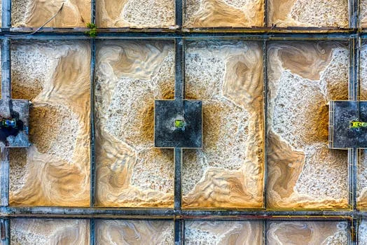
chip fab fluoride wastewater treatment - Fluoride Removal Mechanisms: Chemical Precipitation vs. Alternative Technologies
Calcium precipitation remains the gold standard for high-concentration fluoride removal in semiconductor fabs, achieving 95-99.5% efficiency by forming insoluble calcium fluoride (CaF₂) precipitates. This process typically involves dosing lime (Ca(OH)₂) or calcium chloride (CaCl₂) into the fluoride-laden wastewater, initiating the chemical reaction: Ca²⁺ + 2F⁻ → CaF₂↓. The optimal pH range for this reaction is generally 8–11, with fine-tuning often required to balance precipitation efficiency against co-contaminant removal and scaling potential. A significant byproduct of this method is sludge generation, typically ranging from 0.5–1.2 kg of dry sludge per kilogram of fluoride removed, which requires subsequent dewatering and disposal. While highly effective, calcium precipitation faces limitations such as silica interference, which can hinder CaF₂ crystal growth, and potential scaling on equipment surfaces if not properly managed.
Alternative technologies offer distinct advantages for specific fluoride concentrations, wastewater volumes, and polishing requirements:
Ion Exchange (IX): This method uses specialized resins (e.g., alumina-based or strong base anion resins) that selectively adsorb fluoride ions. Ion exchange can achieve 90–98% removal efficiency, particularly effective for lower fluoride concentrations or as a polishing step. However, it requires periodic regeneration of the resin, typically with an acid or caustic solution, generating a concentrated fluoride brine that needs further treatment. Operational costs are estimated at $0.50–$2.00 per 1,000 gallons treated, primarily for resin regeneration chemicals and disposal of spent regenerant.
Adsorption: Materials like activated alumina or bone char can adsorb fluoride ions onto their surface. Adsorption capacities typically range from 1–4 mg F⁻/g media, making it suitable for low-flow streams or point-of-use treatment. Adsorption is highly pH-dependent, with optimal performance often in the acidic to neutral range (pH 5–7). Media replacement frequency depends on influent fluoride concentration and flow rate, contributing to operational costs.
Electrocoagulation (EC): This electrochemical process uses sacrificial anodes (often aluminum or iron) that release metal ions into the wastewater, forming coagulants that destabilize fluoride ions and other contaminants. EC can achieve 90–97% fluoride removal, consuming 0.5–2 kWh/m³ of energy. It is particularly suitable for small fabs or as a pre-treatment step due to its compact footprint and ability to remove a broad range of pollutants, but can generate metal hydroxide sludge.
Membrane Processes (RO/NF): Reverse Osmosis (RO) and Nanofiltration (NF) membranes offer high rejection rates (90–98%) for fluoride and other dissolved solids. However, their high energy consumption and susceptibility to fouling by silica, organics, and scaling agents (like calcium fluoride) make them less suitable as primary fluoride treatment. They are typically employed as a polishing step within a ZLD system, downstream of chemical precipitation, to achieve stringent water reuse targets.
Energy consumption, metal sludge, electrode consumption
Pre-treatment, small fabs
Membrane (RO/NF)
90–98%
Physical separation
High purity effluent, ZLD integration
High energy, fouling risk, requires pre-treatment
Polishing, ZLD systems
Engineering Specs for Chip Fab Fluoride Wastewater Treatment Systems
Optimizing chip fab fluoride wastewater treatment systems requires precise engineering specifications, including influent characteristics ranging from 250–1500 mg/L fluoride and pH 2–12, to ensure effective contaminant removal and regulatory compliance. Influent variability is a critical design consideration. Fluoride concentrations can fluctuate significantly based on fab operations, along with pH (acidic from etching, alkaline from cleaning), silica (50–300 mg/L from CMP and etching), and total suspended solids (TSS, 100–500 mg/L). Co-contaminants like TMAH and heavy metals also demand attention. To manage this variability, equalization tanks are essential, typically designed for 4–8 hours of hydraulic retention time (HRT) to buffer fluctuations and ensure consistent feed to the treatment system.
Chemical dosing is the heart of calcium precipitation. For lime (Ca(OH)₂) or calcium chloride (CaCl₂) dosing, a molar ratio of 1.5–2.5:1 Ca:F is commonly applied to ensure complete precipitation and account for competing reactions. pH adjustment is critical, often achieved using caustic (NaOH) or acid (H₂SO₄) to maintain the optimal pH range of 8–11. Flocculants, such as anionic or non-ionic polyacrylamides (PAM), are typically dosed at 1–5 mg/L to enhance the aggregation of CaF₂ precipitates for efficient separation. For a flow of 100 m³/h with 1000 mg/L F⁻, a 2:1 Ca:F molar ratio would require approximately 120 kg/day of Ca(OH)₂ (90% purity). Automated chemical dosing systems, like Zhongsheng Environmental's automatic chemical dosing system, are crucial for precise control and minimal operator intervention.
A typical process flow for chip fab fluoride treatment involves:
Equalization: Homogenizes influent wastewater.
pH Adjustment: Raises pH to 8–11 for optimal CaF₂ precipitation.
Coagulation: Rapid mixing for chemical dispersion and initial precipitate formation.
Flocculation: Gentle mixing to promote floc growth with flocculant addition.
Sedimentation: Clarifier (e.g., lamella clarifier) for gravity separation of CaF₂ sludge.
Filtration: Multi-media filters (sand, anthracite) or cartridge filters for polishing effluent and removing residual suspended solids.
Polishing: Further treatment (e.g., ion exchange or membrane filtration) may be required for stringent discharge or reuse targets.
Total retention times for this sequence typically range from 2–4 hours. Footprint estimates vary widely but average 0.5–2 m² per m³/h capacity, depending on clarifier type and integration.
Automation requirements are stringent for semiconductor fabs. Programmable Logic Controllers (PLCs) are used for continuous monitoring and control of key parameters such as pH, Oxidation-Reduction Potential (ORP), and online fluoride sensors. Remote monitoring capabilities are essential for real-time data acquisition, compliance reporting, and predictive maintenance. Fail-safe alarms for chemical dosing systems prevent over-dosing or under-dosing, which could lead to permit violations or equipment damage.
Sludge handling is a critical, often underestimated, component. The generated CaF₂ sludge, mixed with other metal hydroxides and silica, requires dewatering. Plate and frame filter presses are standard, with specs typically ranging from 10–50 m² filtration area, achieving cake solids content of 30–50%. This dewatered sludge is usually disposed of in hazardous waste landfills. However, research into CaF₂ recovery and recycling for applications in industries such as metallurgy is ongoing, offering potential future sustainability benefits. Zhongsheng Environmental offers filter press for dewatering fluoride sludge, designed for robust industrial applications.
Cost Breakdown: Fluoride Treatment Systems for Semiconductor Fabs
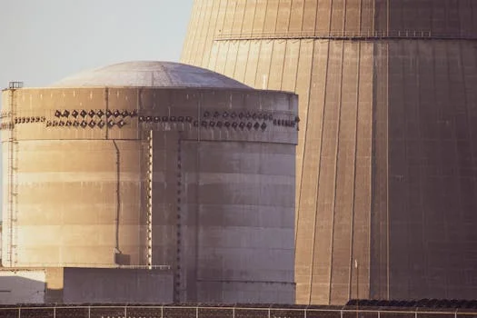
chip fab fluoride wastewater treatment - Cost Breakdown: Fluoride Treatment Systems for Semiconductor Fabs
The capital expenditure (CAPEX) for a typical 50–500 m³/h fluoride treatment system in a semiconductor fab ranges from $500,000–$3M, with operational expenditure (OPEX) significantly influenced by chemical and sludge disposal costs. CAPEX primarily covers the acquisition of equipment, including reactors, clarifiers, automated chemical dosing systems, filtration units, and the sophisticated PLC-based automation infrastructure. Site preparation, encompassing civil works, foundations, and utility connections, typically adds 10–20% of the equipment cost, while installation and commissioning can account for another 15–30%. These figures can vary based on system complexity, required redundancy, and specific fab site conditions.
Operational expenditure (OPEX) is a critical long-term consideration. Chemical costs, predominantly for lime or calcium chloride, pH adjusters (NaOH/H₂SO₄), and flocculants, typically fall between $0.20–$0.80 per m³ treated, depending on influent fluoride concentration and chemical market prices. Energy consumption, primarily for pumps, mixers, and dewatering equipment, adds $0.05–$0.20 per m³. Labor costs, often requiring 1–2 full-time equivalent (FTE) technicians for a 200 m³/h system, are also a significant component. Sludge disposal, especially for hazardous fluoride-laden sludge, can range from $50–$200 per ton, making sludge volume minimization crucial.
Return on Investment (ROI) for fluoride treatment systems is driven by multiple factors beyond simple compliance. Direct savings from water reuse, ranging from $1.50–$5.00 per m³ for high-purity water, can quickly offset OPEX. Avoiding regulatory fines, which can escalate from $10,000 to over $100,000 per violation, provides substantial risk mitigation. participation in ZLD initiatives and water reuse projects may qualify fabs for incentives, such as tax credits under the CHIPS Act, further enhancing ROI.
Technology
CAPEX (50–200 m³/h)
OPEX (per m³)
Footprint (m²/m³/h)
Scalability
5-Year TCO (200 m³/h)
Calcium Precipitation
$0.8M – $2M
$0.40 – $1.00
0.8 – 1.5
High
~$4.5M – $8.0M
Ion Exchange
$1.2M – $2.5M
$0.70 – $2.50
0.5 – 1.0
Medium
~$6.0M – $12.0M
Adsorption (Large Scale)
$0.5M – $1.5M
$0.60 – $2.00
0.6 – 1.2
Low-Medium
~$4.0M – $9.0M
Note: 5-Year TCO (Total Cost of Ownership) includes estimated CAPEX, chemicals, energy, labor, and sludge disposal for a 200 m³/h system operating 24/7. Costs are indicative and vary by region and specific design.
When selecting a vendor for fluoride treatment systems, engineers and procurement teams should ask key questions to ensure a fit-for-purpose solution. These include: "What’s your guaranteed fluoride removal efficiency at our specific influent concentration (e.g., 1500 mg/L) and flow rate?", "How do you specifically address silica interference in your design, and what are the associated operational implications?", and "Can you provide a detailed CAPEX/OPEX breakdown and a lifecycle cost analysis for our projected wastewater volume and fluoride load?" A comprehensive real-world case study of fluoride wastewater treatment in a semiconductor fab demonstrates the practical application of these principles.
Integrating Fluoride Treatment into Zero-Liquid-Discharge (ZLD) Systems
Integrating fluoride treatment as a critical pre-treatment step within a Zero-Liquid-Discharge (ZLD) system is essential for semiconductor fabs aiming for 90%+ water recovery and long-term sustainability. A typical ZLD system flow for chip fab wastewater begins with robust pre-treatment, including effective fluoride removal, followed by advanced membrane separation and thermal processes. The sequence generally involves: fluoride treatment (primary removal) → ultrafiltration (UF) / microfiltration (MF) → reverse osmosis (RO) / nanofiltration (NF) → electrodialysis reversal (EDR) → crystallizer/evaporator. This multi-stage approach can achieve water recovery rates of 90–98%, but it is energy-intensive, with consumption typically ranging from 5–15 kWh/m³ depending on the target recovery and specific technologies employed. Zhongsheng Environmental offers advanced RO water purification systems critical for ZLD.
Fluoride treatment plays a pivotal role in ZLD systems by protecting downstream membrane processes from scaling and fouling. High concentrations of calcium fluoride, if not adequately removed, can precipitate on RO/NF membranes, leading to reduced flux, increased cleaning frequency, and premature membrane replacement. Silica, a common co-contaminant in chip fab wastewater, presents a particular challenge; high silica concentrations can interfere with CaF₂ precipitation, reducing its efficiency, and can also polymerize on membrane surfaces, forming hard-to-remove scale. Therefore, effective fluoride and silica removal in the initial stages is paramount for the long-term reliability and cost-effectiveness of the entire ZLD system.
A compelling case study illustrates this integration: a 150 m³/h ZLD system for a U.S. semiconductor fab successfully implemented a multi-stage approach. The process began with chemical precipitation for fluoride and heavy metals, followed by DAF systems for fluoride sludge separation, then ultrafiltration, two-pass RO, and finally, a mechanical vapor recompression (MVR) evaporator for brine concentration. This system achieved 99.5% fluoride removal and 95% water recovery, with a CAPEX of approximately $8.2M and an OPEX of $0.75/m³. The high water recovery significantly reduced the fab's reliance on municipal water and minimized discharge liabilities. For more details on CMP wastewater, see our article on CMP wastewater treatment for semiconductor fabs.
Emerging technologies are continuously improving ZLD performance and energy efficiency. Forward Osmosis (FO), for example, utilizes a semi-permeable membrane and an osmotic pressure differential from a draw solution to treat high-salinity and high-fouling waters with lower energy input than traditional RO. Membrane Distillation (MD) offers another low-energy alternative, using a hydrophobic membrane to separate water vapor from non-volatile components, suitable for highly concentrated brines. These technologies are particularly attractive for their potential to handle challenging waste streams that may bypass or foul conventional membranes.
Technology
Energy Use (kWh/m³)
Typical CAPEX (Relative)
Scalability
Key Advantage
Conventional ZLD (RO + Evaporator)
5–15
High
High
Proven, high recovery
Forward Osmosis (FO)
2–8 (hybrid)
Medium-High
Medium
Low fouling, high salinity tolerance
Membrane Distillation (MD)
1–5 (thermal)
Medium
Low-Medium
Handles high TDS, lower energy for thermal
Compliance and reporting for ZLD systems require rigorous documentation. This includes daily fluoride testing of influent and effluent, detailed records of chemical consumption, sludge generation and disposal records, and regular monitoring of water quality parameters throughout the ZLD train. Integrating these data points with fab-wide Environmental, Health, and Safety (EHS) software streamlines reporting processes, ensures regulatory adherence, and supports continuous operational improvement.
Frequently Asked Questions
chip fab fluoride wastewater treatment - Frequently Asked Questions
What’s the optimal pH for calcium fluoride precipitation?
The optimal pH for calcium fluoride precipitation is generally between 8 and 11, with a narrow range of 9–10 often considered ideal for balancing high fluoride removal efficiency and minimizing potential scaling from other co-precipitants like magnesium hydroxide. At lower pH values, CaF₂ solubility increases, reducing removal efficiency. At excessively high pH (above 11), the formation of calcium carbonate or magnesium hydroxide can become more pronounced, leading to increased sludge volume and potential scaling issues.
How do I handle silica interference in fluoride treatment?
Silica interference in fluoride treatment primarily affects calcium fluoride precipitation by encapsulating CaF₂ crystals, hindering their growth, and reducing settling efficiency. Solutions include pre-treatment with magnesium compounds (e.g., magnesium hydroxide) to co-precipitate silica at a pH of 10–11 before primary fluoride removal. Alternatively, operating the calcium fluoride precipitation at the higher end of the optimal pH range (pH 10–11) can also help with silica removal, though this may increase chemical consumption and sludge volume. Careful pH control and adequate retention times are crucial.
What’s the typical lifespan of fluoride treatment equipment?
The typical lifespan of fluoride treatment equipment varies by component. Reactors and clarifiers, often constructed from robust materials like FRP or lined steel, can last 15–20 years with proper maintenance. Mechanical components such as pumps and mixers generally have a lifespan of 7–12 years. Membranes in polishing stages (RO/NF) typically last 5–10 years, depending on feed water quality and cleaning cycles. Sensors (pH, ORP, fluoride) require more frequent replacement, typically every 1–3 years. Regular preventative maintenance, calibration, and timely replacement of wear parts are key to maximizing equipment longevity.
Can I reuse treated fluoride wastewater in my fab?
Yes, treated fluoride wastewater can be reused in your fab, but it almost always requires further polishing beyond primary fluoride removal to meet stringent fab-grade water quality specifications. This typically involves advanced membrane processes (RO/NF) to remove residual fluoride, dissolved solids, and other contaminants. Common reuse applications for polished fluoride wastewater include non-contact cooling towers, exhaust scrubbers, and certain non-critical utility water uses. For process-critical applications, further purification steps, such as ion exchange or electrodeionization (EDI), would be necessary to achieve ultrapure water (UPW) standards.
What are the most common mistakes in fluoride wastewater treatment?
The most common mistakes in fluoride wastewater treatment for chip fabs include inadequate equalization, leading to fluctuating influent quality that destabilizes treatment; poor pH control, which compromises CaF₂ precipitation efficiency or causes scaling; ignoring silica, which can severely impede fluoride removal and foul downstream equipment; and underestimating sludge handling costs, resulting in budget overruns and operational bottlenecks. Proper system design, robust automation, and a comprehensive understanding of the wastewater matrix are essential to avoid these pitfalls.
Need a customized solution? Request a free quote with your specific flow rate and pollutant parameters.
Zhongsheng Engineering Team
Our team of wastewater treatment engineers has over 15 years of experience designing and manufacturing DAF systems, MBR bioreactors, and packaged treatment plants for clients in 30+ countries worldwide.