Define the wastewater sources before selecting equipment
A Hamamatsu data center needs a stream-specific treatment plan rather than one generic wastewater system. Cooling-tower blowdown requires control of dissolved solids, hardness, suspended solids, corrosion and microbial risk; sanitary wastewater, rack wash water, RO reject and direct-liquid-cooling coolant require separate evaluation. Open-loop evaporative cooling commonly returns only about 20–30% of withdrawn water as liquid blowdown, while closed-loop systems can return approximately 90–95% (KETOS). The design must establish the receiving route and obtain site analyses, flow data, chemical inventory and Japanese permit requirements before selecting equipment.
Begin with a process-flow inventory and a P&ID. Do not combine a continuous cooling purge with a batch wash discharge simply because both eventually reach one drain. For every outlet, record average and peak flow, discharge frequency, source, temperature, pH, chemical inventory and intended destination.
Open-loop evaporative cooling deliberately removes blowdown because evaporation leaves salts and treatment chemicals behind, progressively concentrating the recirculating water (Commercial Water Lab, June 2026). Closed-loop cooling is not discharge-free: leakage, maintenance and incidental losses still require a route. Thermal discharge from free-cooling water is another stream because its primary issue is heat rather than concentration.
Direct-liquid- and immersion-cooling coolant requires specialist review. Commercial Water Lab identifies refrigerants or PFAS compounds as possible constituents requiring specialized handling, particularly for emerging high-density GPU installations. Their presence, concentration and disposal route must be established from the coolant SDS and sampling rather than inferred from the server design.
| Stream | Primary issue to characterize | Minimum project inputs |
|---|---|---|
| Cooling-tower blowdown | Concentrated salts, hardness, suspended solids, biocides and corrosion inhibitors | Average and peak flow; batch frequency; complete chemistry; chemical inventory; temperature; pH; cycles of concentration; outlet |
| Sanitary sewage | Organic matter and pathogens | Fixture discharge, peak factor, authority requirements and proposed sewer connection |
| Rack wash water | Variable solids and possible cleaning residues | Batch volume and frequency, detergent inventory, floor collection method and disposal route |
| RO reject | Concentrated dissolved salts | Feed flow, recovery setting, product-water flow, reject chemistry and final outlet |
| Direct-liquid or immersion coolant | Coolant-specific constituents, including possible refrigerants or PFAS | Fluid identity, SDS, concentration, purge volume, analysis and approved handling route |
| Thermal discharge | Elevated temperature | Withdrawal and return flow, temperature rise, receiving water and mixing information |
Assess data center water recycling effectiveness against these actual streams and operating modes rather than a nominal water-consumption percentage.
Match each discharge stream to its treatment objective
The receiving destination determines the treatment objective, so a discharge route must be confirmed before equipment is specified. Cooling-tower blowdown is a concentrated cooling-water stream that may support industrial wastewater reuse, controlled municipal sewer pretreatment, or surface-water discharge; each route has different quality and documentation requirements.
Thermal discharge requires a separate evaluation from chemical contamination. Commercial Water Lab, citing UGA Extension and EPA guidance in June 2026, reports that warm free-cooling return water can reduce dissolved oxygen, stress aquatic organisms and promote algal blooms. An elevated-temperature assessment therefore needs the receiving-water route and site-specific information even if the water is chemically compliant.
Route sanitary sewage to a dedicated biological treatment train or an approved sewer connection. Mixing it with cooling blowdown can change the contaminant load, biological demand and treatment objective. Rack wash water, RO reject and direct-cooling coolant should each be treated as separate engineering studies. The treatment selected for ordinary cooling blowdown may not fit a detergent-bearing wash stream, saline RO reject or a coolant containing substances requiring controlled handling.
Use this routing logic:
- If discharge is to a municipal sewer, obtain sewer-acceptance and pretreatment requirements before defining the polishing train.
- If discharge is to a river, coastal water or another surface water, establish the receiving-water sensitivity, thermal effects and direct-discharge conditions.
- If water returns to the cooling system, define the allowable chemistry for heat-transfer surfaces, corrosion control and microbial control.
- If a stream is unsuitable for cooling reuse, assign it a compliant disposal route rather than forcing it into the general reuse train.
| Proposed route | Design gate | Information required |
|---|---|---|
| Treatment followed by cooling reuse | Water quality must suit the receiving cooling system | Cooling chemistry limits, heat-transfer constraints, recovery target and operating program |
| Municipal sewer pretreatment | Local acceptance criteria must govern the specification | Applicable sewer rules, discharge permit, pollutant inventory and sampling requirements |
| Surface-water discharge | Direct-discharge requirements and thermal effects must be assessed | Outfall, receiving-water information, authority requirements and temperature evidence |
| Specialist disposal | The stream requires its own handling protocol | Coolant or chemical identity, SDS, laboratory analysis and approved waste handler |
For a discontinuous rack-wash stream, use the separate sizing treatment for rack wash water method rather than applying the cooling-blowdown duty directly.
Characterize Hamamatsu source water and the receiving route
Treatment performance cannot be defended from incoming-water chemistry alone because cooling operation concentrates the contaminants that reach the discharge. Commission representative baseline sampling of Hamamatsu source water, recirculating cooling water and actual blowdown, with sampling points agreed before final equipment selection.
The source-water laboratory request should cover TDS or conductivity, hardness as CaCO₃, alkalinity, silica, chloride, sulfate, pH, turbidity, suspended solids, iron and manganese. Request calcium and magnesium speciation where needed for scale prediction. These parameters must be linked to a saturation or scaling assessment rather than interpreted independently.
Obtain the complete cooling-water operating program: makeup-water temperature, cycles of concentration, chemical products, dosing, bleed rate, expected blowdown flow and anticipated changes in server density. The supplied research does not provide a universal blowdown equation or a Hamamatsu site flow, so neither should appear in a budget quotation as an established value.
Confirm the precise outlet rather than using the word “sewer” generically. It may be a sanitary sewer, stormwater system, river, coastal receiving water or an internal reuse loop. Identify the responsible municipality, sewer administrator and permitting authority in Hamamatsu, then obtain their written requirements.
The Research Institute for Water Technology or the relevant local authority should confirm applicable Japanese water-quality, effluent and sewer-acceptance requirements. The supplied research contains no Hamamatsu-specific numerical limits, so this guide does not invent them. Obtain baseline samples of actual blowdown and any direct-cooling coolant because accumulated discharge chemistry can differ materially from makeup-water chemistry.
- Request a complete cooling-water analysis during normal operation, including chemical-addition impacts.
- Sample across representative operating and blowdown conditions, not only during commissioning.
- Record temperature and pH at each sampling point.
- Confirm whether coolant constituents require separate laboratory methods or specialist disposal.
- Archive chain-of-custody and analytical methods with the permit application.
Select the treatment train around cooling-water reuse
Select unit operations for the contaminant or reuse objective they address, then size them from actual flow and chemistry. Pretreatment protects membranes; softening addresses hardness; DAF removes floatable material and suspended solids; membranes control dissolved salts; and disinfection supports microbial control.
For solid-sensitive reuse, the specified UF pretreatment for cooling-water reuse uses 0.03 μm PVDF membranes, accepts feed turbidity up to 300 ppm, includes automatic backwash and air scour, and is offered from 2,000 to 40,000 L/h. These are equipment specifications, not a statement that the system will meet a Hamamatsu reuse target without feed and flux data.
Where hardness threatens heat-transfer surfaces or downstream membranes, use softening or nanofiltration. The specified industrial water softening for data-center cooling covers 1–45 T/h with paired brine tanks of 60–2,000 L. Softener selection must follow hardness, flow, resin capacity and regeneration-residual calculations.
| Treatment objective | Applicable unit operation | Selection basis | Main issue to verify |
|---|---|---|---|
| Suspended-solids and colloid control | UF | Feed turbidity, flow, temperature and required flux | Fouling, cleaning and concentrate |
| Hardness and scale control | Twin-tank softener or NF | Hardness as CaCO₃, flow and downstream sensitivity | Regeneration waste or NF reject |
| Oil, colloids, FOG and floatables | DAF | Load, particle characteristics and recovery | Sludge removal and chemical use |
| Microbial control | Disinfection | Target organisms, residual and contact requirements | By-products, corrosion and dosing control |
| Dissolved-solids reduction | RO or NF | Feed chemistry, recovery and product-water target | Energy and concentrate disposal |
Genesis Water Technologies (2026) reports general cooling make-up design references of 500–1,500 mg/L TDS, 200–400 mg/L hardness as CaCO₃, 10–25 mg/L suspended solids, pH 6.5–8.5 and 50–200 mg/L alkalinity as CaCO₃. These are design-reference ranges, not Hamamatsu discharge limits or automatic reuse criteria.
When comparing UF and RO, include lifecycle energy, concentrate disposal, chemical demand and recovery. Genesis Water Technologies reports that NF can reduce energy use by 30–40% versus RO for targeted hardness removal. A separate RO train cited by Genesis achieved 88% overall recovery and 98% TDS reduction; that project result cannot be transferred to this site without matched feed conditions.
Reuse also requires lifecycle assessment rather than an automatic environmental claim. Open Engineering Inc’s 2026 preprint found approximately twice the global warming potential for its wastewater-reuse scenario and attributed roughly 80% of the difference to treatment energy. The scenario does not determine the Hamamatsu outcome, but it shows why energy and concentrate must be included in route comparison.
Size treatment from flow, chemistry and recovery
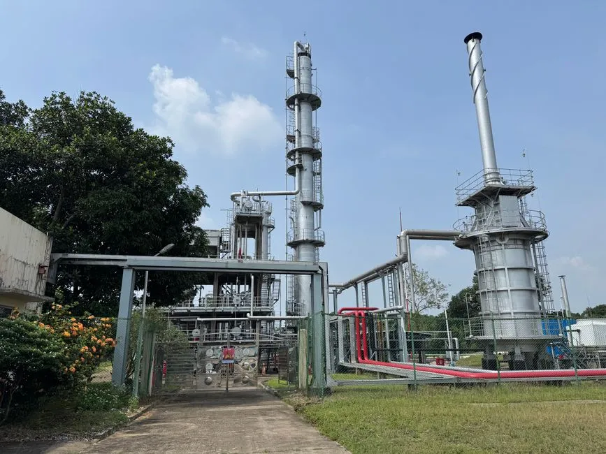
Size each continuous and batch stream separately. A cooling purge, rack-wash discharge, sanitary peak, RO reject and membrane concentrate should not be averaged into one nominal flow, because their operating schedules, storage requirements and acceptance criteria differ.
The design flow sequence is:
- Determine continuous blowdown and the selected cycles of concentration from the site water balance.
- Add periodic control discharges according to their frequency and volume.
- Calculate separate peaks for sanitary wastewater, rack washing and membrane reject.
- Apply the selected treatment train’s recovery to derive product water and residual reject.
- Check tanks, membranes, transfer pumps and treatment equipment against continuous duty and peak intermittent duty.
The supplied research does not provide a universal blowdown formula or a Hamamatsu flow, so a numerical equipment duty should remain conditional until makeup, evaporation and cycles-of-concentration data are approved. For tanks and transfer systems, assess whether the greater of average continuous duty and peak intermittent duty governs, then verify storage and operating sequences for the recovery and reject streams.
Prepare a mass balance covering incoming water, evaporation, concentrated blowdown, reuse return, final discharge, sludge and concentrate removal. This is the auditable basis for any water-reuse-recovery claim. Include drift and other unmeasured losses where the site metering plan cannot account for them.
Use Water Usage Effectiveness and site-water-balance metrics alongside flow. KETOS reports an industry-average WUE around 1.8 L/kWh and a practical data-center range of about 1–9 L/kWh. These figures are benchmarking context, not Hamamatsu design inputs, and should not replace an IT-energy denominator and site-specific water balance.
Equipment sizing should also test the consequences of uncertainty. Run sensitivity cases for lower makeup flow, higher cycles of concentration, unexpected batch discharges, membrane recovery decline and temporary reject disposal. If these cases change the selected equipment, the input is not yet design-ready.
Build a compliance and operating assurance plan
A permit matrix must connect each outlet and stream to its authority, application route, analytical requirements and operating responsibility. The matrix should be maintained through detailed design, commissioning and operation because a change in outlet, chemical inventory or cooling configuration may change the applicable assessment.
For cooling-related streams, the monitoring plan should include conductivity or TDS, pH, suspended solids, hardness, residual biocide, metals where justified by the cooling chemicals, and temperature for thermal discharge. Add coolant-specific constituents where the direct-liquid- or immersion-cooling assessment identifies them.
| Assurance item | Minimum documentation | Operational response |
|---|---|---|
| Permit and authority | Applicable requirement, application, approval and monitoring frequency | Do not change the outlet or treatment objective without formal review |
| Cooling chemistry | Cycles of concentration, chemical products, dosing and residual biocide records | Adjust the chemical program within the approved operating envelope |
| Equipment condition | Flow, pressure, differential pressure, conductivity and cleaning records | Investigate deviation before fouling or compliance risk develops |
| Source-water change | Periodic laboratory analysis and trend review | Revisit pretreatment, softening or membrane settings |
| Off-spec water | Alarm, isolation, sampling and approved disposal route | Divert to the contingency route and notify the responsible operator |
| Commissioning | Performance tests, calibration, bypass rules and operator training | Accept the train only after the specified duties are demonstrated |
Tie treatment operation to the cooling program. Scaling and corrosion inspections should verify whether the combined chemical and membrane strategy maintains the intended cooling-water condition. Biocide dosing must be reconciled with any separate disinfection equipment so the system does not create an unintended chemical or discharge burden.
Use online or frequent monitoring to identify changes in source chemistry, blowdown concentration, biofilm risk and membrane differential pressure. A trend alarm is more useful than a single compliance sample because it shows whether the process is moving outside its operating envelope.
Document sampling points, flow meters, calibration, chemical inventory, safety controls, bypass rules, commissioning tests and contingency disposal for reject or off-spec water. Where an analyzer is required, define its role rather than treating it as independent proof of compliance.
Prepare the supplier brief and choose the best-fit route
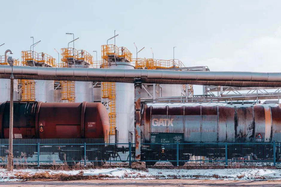
A procurement-ready brief should contain enough site information for bidders to define a guaranteed duty and expose commercial assumptions. Without it, quotations cannot be compared fairly.
Provide the source-water and blowdown analyses, stream-by-stream flows, cooling-system P&ID, chemical inventory, temperature, cycles of concentration, recovery target, receiving destination and written permit constraints. Ask each bidder to state guaranteed duty flow, product-water quality, reject flow and quality, availability, recovery, cleaning requirements, chemical consumption, controls and monitoring scope.
| Route | Indicative scope | Key decision test | Costs to include |
|---|---|---|---|
| Treat for compliant discharge | Pretreatment and any required polishing before the specified outlet | Can the bid demonstrate compliance with the confirmed route? | Equipment, media, chemicals, energy, sludge, maintenance and monitoring |
| Treat and reuse | Recovery train, storage, pumping and return controls | Does product water remain suitable as the cooling-system changes? | Treatment, recovery, concentrate, downtime and replacement cycles |
| Minimize blowdown operationally | Cooling-program or control changes that reduce purge without creating unacceptable scaling or corrosion risk | What site evidence supports the proposed cycles of concentration? | Chemical changes, monitoring, energy and operational risk |
Evaluate routes by total lifecycle cost and permit risk, not equipment price alone. Include membranes or media, energy, chemicals, sludge or concentrate management, operator attention, shutdowns and replacement cycles. A lower first-cost package can be more expensive if it relies on frequent cleaning or creates a reject stream with no approved outlet.
Require the proposal to be adjusted for Hamamatsu source-water chemistry. Generic package drawings based only on feedwater quality are inadequate because cooling blowdown carries accumulated treatment chemicals and concentrates the recirculating water. Bidders should identify where the proposal depends on further testing.
Use pilot testing when variability, scaling, biological growth or a high-risk discharge stream makes it necessary for procurement confidence. Pilot results should be tied to the same acceptance criteria proposed for the full installation. No route should advance until its performance, reject route and compliance evidence are defined.
Frequently Asked Questions
What will treatment for cooling blowdown cost in Hamamatsu?
No defensible price can be given without the treatment objective, average and peak flow, source and blowdown analyses, recovery target and receiving route. Request a first-cost quotation plus lifecycle costs for energy, chemicals, membrane or media replacement, sludge or concentrate disposal, maintenance and monitoring; the supplied research contains no Hamamatsu equipment pricing.
How should treatment capacity be sized for the data center?
Size each stream separately from continuous blowdown, batch discharges, sanitary wastewater, wash water and membrane reject. The supplier must show continuous and peak duty, storage assumptions, recovery and reject flow; nominal capacity alone is not an acceptable sizing basis.
Which supplier qualification reduces technical and compliance risk?
Require a proposal tied to the site P&ID, actual water analyses, cooling chemicals and written receiving-route requirements. Check guaranteed flow, product-water and reject quality, availability, controls, cleaning, maintenance support and contingency disposal before comparing commercial terms.
Can cooling blowdown be reused for industrial wastewater recovery?
It can be considered only after the actual blowdown chemistry, cooling-system limits, recovery objective and downstream use are defined. UF, softening, DAF, membranes and disinfection address different contaminants, so reuse requires a complete train and a water balance rather than automatic return to the cooling loop.