Why a Fes data center needs a dedicated water and blowdown strategy
A Fes data center cannot treat water as a passive utility input. A 100 MW facility can consume up to ~2 million liters of water per day, and IDE Tech notes that industry-wide water demand is projected to intensify through 2026 as AI workloads scale. Fes sits in a Mediterranean-to-semi-arid climate where summer wet-bulb temperatures compress the cooling-tower approach and lift evaporation losses above temperate-site baselines; the engineering consequence is a larger blowdown volume per MW than a peer plant in northern Europe.
At 4 cycles of concentration, cooling-tower blowdown typically equals 25–30% of makeup water, so a 10 million-gallon-per-month facility would discharge 2.5–3 million gallons (Genesis Water Tech). In water-stressed regions, direct discharge fees already run US$5–15 per 1,000 gallons, and some jurisdictions cap discharge TDS below 1,500 mg/L (Genesis Water Tech) — both data points that apply to a Fes cost case once the current Moroccan decree is confirmed against the project site. The Fes developer client will track PUE and WUE as site-selection gates, and water is shifting from an O&M afterthought to a permit precondition. The U.S. DOE FEMP cooling-water guide frames the same levers: raising cycles from three to six cuts makeup water 20% and blowdown 50% at no capital cost, which is why a Fes plan always starts there before any membrane or thermal skid is ordered.
The two wastewater streams a Fes data center actually produces
The single most common scoping error in early data-center water plans is conflating two streams that need separate treatment packages. Stream 1 is cooling-tower blowdown: brackish, with TDS typically 1,200–6,000 mg/L, hardness and silica concentrated 4–8× above makeup, suspended solids 10–50 mg/L, plus accumulated biocide, corrosion inhibitor, scale inhibitor and dispersant residues (Genesis Water Tech). This is the recovery target — high-volume, scale-prone, and the reason reverse osmosis belongs in the design. Stream 2 is on-site domestic sewage from staff, cafeteria and restrooms: far lower flow, biodegradable, governed by a different discharge rule and normally handled in a packaged biological skid. An optional Stream 3 covers humidification bleed-off, chiler-side flush water, and periodic fire-test water; it is typically routed to the sanitary train because its volume is small and its contaminants are amenable to biological treatment. The engineering consequence for a Fes campus is two parallel trains: a high-recovery RO/MVC train for Stream 1 sized to blowdown flow, and a compact MBR or A/O skid for Stream 2 sized to staff population. Treating them in a single oversized unit wastes energy on the sanitary side and starves the membrane train of the recovery it needs to pay back.
A reference treatment train for Fes cooling-tower blowdown
The process flow below is the defensible baseline for a Fes CTBD train. Each stage has a specific job, and the membrane stage is where Fes feed-water chemistry most often forces a deviation from a generic U.S. layout.
Stage 1 — Side-stream filtration: self-cleaning spiral or disc filters at 10–25 µm drop suspended solids and biological loading from a side bleed of the recirculating loop, enabling higher cycles of concentration. Size the unit at 1–5% of circulation flow, and budget US$50,000–200,000 for a typical installation (Genesis Water Tech). For Fes, this stage pays back first because the local feed has historically been HCO3-rich and moderately hard — a multi-media pretreatment filter ahead of the membranes reduces SDI excursions during summer dust events.
Stage 2 — Pretreatment polish: a multi-media filter trimmed to <10–15 µm, paired with antiscalant injection and pH adjustment. Genesis Water Tech notes that feed conditioning to this level is the difference between an RO skid that runs six months between cleanings and one that fouls in six weeks.
Stage 3 — Reverse osmosis: the recovery target. RO delivers 95–99% salt rejection with permeate TDS of 10–50 mg/L, suitable for direct return as cooling-tower makeup. Recovery on conventional brackish water RO (BWRO) plateaus at 75–80% before silica and calcium sulfate scaling dominate; the published Fes-style flow path is 50–85% on the first pass with antiscalant allowing a conservative first stage and a high-recovery second pass where silica allows (Genesis Water Tech). IDE Tech's industry framing makes the same point: pushing BWRO past 75–80% recovery with conventional multi-stage layouts adds booster pumps, interstage boosting, and chemical load. A standard industrial reverse osmosis skid covers this stage.
Stage 4 — High-recovery polish (optional): controlled-precipitation plus dynamic RO pushing the train to roughly 95% overall recovery. This is the architecture behind IDE Tech's MAXH₂O Brine Desalter, which deactivates scale inhibitors in a fluidized bed to drop silica, calcium carbonate and similar salts out as dense pellets, then operates a closed-loop RO on the now NaCl-dominant brine. Permeate silica drops to about 1 mg/L, and the operator can run higher cycles of concentration without pushing the membrane into unstable regimes.
Stage 5 — MVC or brine concentrator (optional, ZLD-near): mechanical vapor compression delivers distillate TDS <10 mg/L at 15–25 kWh per 1,000 US gallons, with 95–98% recovery of the concentrate stream (Genesis Water Tech). Capital runs US$1–3M for 10,000–30,000 GPD capacity. Full ZLD adds a crystallizer and reaches 95–99% overall water recovery with solid salt cake for disposal; CAPEX is US$3–8M and OPEX US$5–15 per 1,000 gallons treated (Genesis Water Tech) — justified only when discharge is prohibited or freshwater is unavailable.
| Stage | Equipment | Typical removal / output | Fes-specific watch-out |
|---|---|---|---|
| 1. Side-stream filtration | Self-cleaning spiral/disc filter, 10–25 µm | SS to <10 mg/L; enables higher COC | Size 1–5% of circulation flow |
| 2. Pretreatment | Multi-media filter + antiscalant + pH trim | SDI guard to <10–15 µm | Summer dust loads; HCO3-rich feed |
| 3. Reverse osmosis | BWRO, FRP vessels, energy recovery | 95–99% rejection; permeate 10–50 mg/L TDS; 50–85% recovery | Silica scaling caps first pass at 75–80% |
| 4. High-recovery polish (optional) | Controlled precipitation + dynamic RO | ~95% overall recovery; permeate silica ~1 mg/L | Verify against Fes site water analysis |
| 5. MVC / ZLD (optional) | Mechanical vapor compression + crystallizer | Distillate <10 mg/L TDS; 95–99% recovery | Hold in reserve for permit tightening |
Sanitary and process wastewater for a Fes campus
The sanitary train sits beside the CTBD skid, not inside it. A packaged MBR or buried A/O unit sized to the staff population handles BOD, suspended solids and disinfection in one skid with minimal operator attention — the packaged MBR sanitary train typical of this duty class. Where on-site irrigation or toilet-flush reuse is intended, an MBR flat-sheet or UF polish stage brings effluent close to reuse quality, but the operator must confirm current ONEE/RADEEMA reuse guidance before sizing for any specific end use. Disinfection by UV or on-site generated chlorine dioxide avoids the regulated chlorinated by-products that would complicate a membrane train downstream and is the standard choice where the sanitary skid discharges to a polishing stage. Flow from humidification bleed-off, chiller flushes and periodic fire-test water is normally routed to the sanitary train because its contaminants are biodegradable and its volume is small.
Sizing and equipment checklist for a Fes deployment
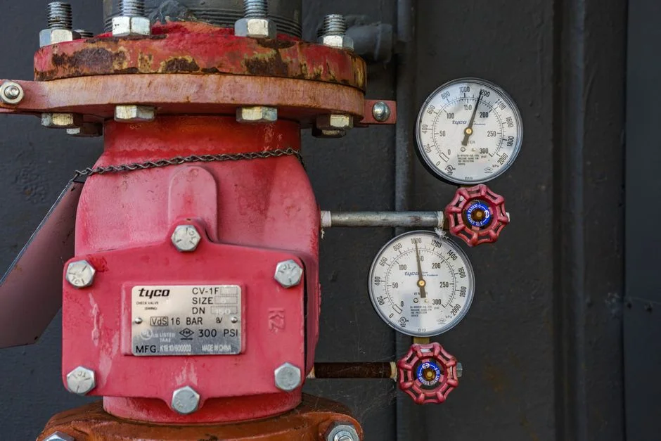
Turn the process flow into a procurement list. The first and most decisive input is a current site feed-water analysis: TDS, hardness (as CaCO3), alkalinity, silica, chloride, free chlorine, iron and manganese. Fes municipal water has historically been HCO3-rich and moderately hard, but only a current sample is decisive — that single document drives the RO recovery target, the antiscalant selection, and whether a softener or nanofiltration pre-pass is more economic than a conventional BWRO first stage. On the cooling-tower side, specify stainless or FRP internals rated for the cycles of concentration the reuse plant will run; a lower-rated fill will scale and fail within the first summer.
For the RO skid, specify FRP pressure vessels, energy-recovery on the larger units, and a PLC with remote telemetry so the Fes site can be monitored from a network operations center. On the discharge side, budget an equalization tank, pH trim, TSS polish, and a flow meter tied into the discharge permit — the operator cannot prove compliance without a metered, logged stream. Finally, specify spare membranes, housings and dosing spares as a single package so the Fes site is not held hostage to import lead times; the procurement schedule should treat consumables as long-lead items. The RO membrane design criteria 2026 guide covers membrane-area math, flux and recovery limits in more detail.
| Item | Specification | Why it matters in Fes |
|---|---|---|
| Feed-water analysis | TDS, hardness, alkalinity, silica, Cl, free Cl2, Fe/Mn | Drives recovery target and antiscalant choice |
| Cooling-tower internals | Stainless or FRP, rated for high COC | Survives cycles a reuse plant will run |
| RO skid | FRP vessels, energy recovery, PLC + telemetry | Enables off-site monitoring |
| Discharge package | EQ tank, pH trim, TSS polish, metered outlet | Required for permit proof |
| Spares package | Membranes, housings, dosing consumables | Mitigates import lead times |
Cost, compliance and decision framework for Fes
The first lever is free. Raising cycles of concentration from 3 to 6 cuts makeup water 20% and blowdown 50% with no capital cost (U.S. DOE FEMP, via the FEMP cooling-water guide). Once cycles are pushed, the next decision is side-stream filtration: a typical skid installs for US$50,000–200,000 (Genesis Water Tech) and enables the cycles the operator wants to run. A 50,000 GPD blowdown RO skid installs for roughly US$250,000–500,000, with operating cost around US$1.50–3.00 per 1,000 gallons treated including energy, chemicals, membrane replacement and maintenance (Genesis Water Tech). MVC for 10,000–30,000 GPD of concentrate runs US$1–3M CAPEX at 15–25 kWh/1,000 US gallons (Genesis Water Tech). Full ZLD for data-center duty is US$3–8M CAPEX with US$5–15 per 1,000 gallons OPEX (Genesis Water Tech), justified only when discharge is prohibited or fresh water is unavailable.
For a Fes plant, the cost case usually points to a partial-recovery stack: high cycles, side-stream filtration, single- or two-pass RO at conservative recovery, and permeate reuse as cooling-tower makeup. MVC belongs in the design as a reserve option for permit tightening or capacity growth, not as a Day-1 commitment. The compliance case must be confirmed against the current Moroccan decree and ONEE/RADEEMA pre-check, but the technical levers above map cleanly to that review. A filter press on the controlled-precipitation stage handles the small solids stream that comes out of a high-recovery polish without sending it to drain.
| Option | CAPEX range | OPEX | When it pays in Fes |
|---|---|---|---|
| Cycles 3 → 6 only | US$0 | 20% makeup / 50% blowdown reduction | Always — first move |
| Side-stream filtration skid | US$50,000–200,000 | Minimal | Enables higher COC |
| Blowdown RO (50,000 GPD) | US$250,000–500,000 | US$1.50–3.00 / 1,000 gal | Reuse as cooling-tower makeup |
| MVC polish (10,000–30,000 GPD) | US$1–3M | 15–25 kWh / 1,000 gal | Permit tightening, capacity growth |
| Full ZLD | US$3–8M | US$5–15 / 1,000 gal | Discharge prohibited, no freshwater |
Frequently Asked Questions
What CAPEX should a Fes data center budget for a CTBD reuse train?
A single-pass RO skid sized to about 50,000 GPD of blowdown installs in the US$250,000–500,000 range, with OPEX around US$1.50–3.00 per 1,000 gallons treated including energy, chemicals, membrane replacement and maintenance (Genesis Water Tech). For a Fes-specific budget, the operator should request a current feed-water analysis and a site-specific flow model from the RO vendor; the recovery target and the number of passes shift the price more than skid size does. Side-stream filtration and high cycles of concentration should be modeled first because they reduce the flow the RO skid has to handle.
How do I pick a treatment supplier for a Fes data center project?
Shortlist suppliers that can show operating references on cooling-tower blowdown at high recovery (75–95%) and that will commit to a feed-water analysis review before quoting. A vendor who quotes a fixed CAPEX without seeing the Fes site water analysis is a flag — Genesis Water Tech is explicit that recovery is scaling-limited and that the recovery target depends on the specific silica, hardness and alkalinity profile. Confirm the supplier's lead time on FRP vessels, energy-recovery devices and spare membranes; for a Fes import path, ask for a spares package bundled with the skid so the site is not held hostage to shipping windows.
When does a Fes data center need zero liquid discharge?
ZLD is justified only when discharge is prohibited or freshwater is genuinely unavailable (Genesis Water Tech). For most Fes sites, the cost-effective target is a high-recovery RO train with permeate reused as cooling-tower makeup and MVC held as a reserve for permit tightening or capacity growth. Full ZLD at US$3–8M CAPEX and US$5–15 per 1,000 gallons OPEX is a permit-driven decision, not a default one — the operator should request the current Moroccan draft discharge decree and confirm the specific TDS, heavy-metal and biocide limits before committing to a crystallizer.
What local factors most change the blowdown design in Fes?
Three inputs drive the deviation from a generic CTBD layout: the ambient wet-bulb profile, the feed-water hardness and alkalinity, and the current ONEE/RADEEMA discharge pre-check. Fes summer wet-bulb conditions push evaporation losses above temperate baselines and so enlarge the blowdown stream per MW. Fes municipal water has historically been HCO3-rich and moderately hard, which interacts with cycles of concentration to set the silica and calcium carbonate scaling ceiling — that ceiling is what caps BWRO at 75–80% recovery in a conventional layout (IDE Tech). The operator must request a current site water analysis and the current Moroccan draft discharge values; both are decisive for sizing the RO recovery target, the antiscalant program, and whether MVC is needed on Day 1. For a comparable regional blueprint, see the Matola data-center blowdown treatment blueprint and the Arequipa data-center blowdown treatment blueprint.
Related Equipment
- packaged MBR sanitary train — specifications, capacity range, and technical data
- PLC-controlled antiscalant and biocide dosing — specifications, capacity range, and technical data