What the Point-of-Use Connection Is — and Why It Is Different From the Rest of the UPW Loop
The point-of-use (POU) connection is the wetted section between the final polishing filter and the process tool dispense, not the polishing skid itself. In a semiconductor UPW system it is the last metre of plumbing that hands the loop's specification — 18.2 MΩ·cm resistivity at 25 °C, TOC under 1 ppb for SEMI F63, particles under 0.3/mL above 0.05 µm, sub-ppb silica — to the wafer. Mixed-material avoidance means specifying that last metre so dissimilar metals, polymers, and elastomers cannot leach ions, organics, or particles into the water. In practice this maps to all-polymer wetted flow paths (PFA or PVDF), 316L SS or higher-grade metallic components where metals are unavoidable, perfluorinated elastomers (FKM/FFKM) at seals, and elimination of brass, Buna-N, EPDM, and standard carbon-steel fittings downstream of the final polishing filter.
What separates the POU from the rest of the loop is recyclability. Water in the central polishing loop is continuously cycled through the polisher; an excursion is caught by online resistivity, TOC, and particle meters and is recycled back into the system (AXEON, ultrapure water systems guide, 2025). Water at the POU is on its way to the wafer, not back to the polisher. The polishing skid is the last place a fab can recover an error in the water; the POU is the last place an error can be made before the error becomes a defect on a sub-7 nm feature.
The POU therefore has to be engineered against the same SEMI F63 and ASTM D5127 end targets as the loop, but with different priorities. Inside the loop, biofilm control, degasser performance, and mixed-bed exhaustion dominate. At the POU, what dominates is the wetted surface area of the dispense path itself: the last 0.5–1.0 m of tubing, the dispense manifold, the diaphragm valve seats, the instrument tees, and the end-fitting that mates to the tool. Each of those is a candidate source of the very contaminants the polisher has just removed.
Wikipedia's overview of ultrapure water (en.wikipedia.org, Ultrapure water) frames the particle problem as one of "particles from the walls of the fluid handling system", which is exactly the POU. The same source notes that filters with pore sizes ≤200 nm are placed just before distribution, and that all particles above half the smallest feature size must be removed. For sub-7 nm logic, that target is particles above ~3 nm, well below the 0.05 µm laser particle counter channel — the practical floor of online metrology. The implication is that the POU cannot be audited only by the counter; it has to be specified by wetted material, because material is what determines what slips below the counter's detection floor.
SEMI F63 and the POU-Side Parameter Budget
The POU budget is the fab-level SEMI F63 / ASTM D5127 specification, restated as targets the dispense path has to deliver — not the targets the polish skid has to leave behind. The difference matters because the POU is downstream of the polish filter and is allowed almost no margin for further degradation.
| Parameter | POU target | Measurement |
|---|---|---|
| Resistivity | >18.2 MΩ·cm at 25 °C | Inline conductivity cell at the dispense manifold |
| TOC | <1 ppb (SEMI F63); <0.5 ppb at sub-7 nm | UV-persulfate online analyser (AXEON, 2025) |
| Particles (≥0.05 µm) | <0.3 particles/mL; tightened by the "half-feature-size" rule (Wikipedia, Ultrapure water) | Laser particle counter at POU |
| Silica (dissolved + colloidal) | Sub-ppb; <0.3 ppb per AXEON summary | ICP-MS at dispense |
| Dissolved O₂ | <10 µg/L at advanced microelectronics | Optical fluorescence DO sensor (Wikipedia, Ultrapure water) |
| Sodium | Low ppb / sub-ppb; leading-edge indicator of cation-exchanger breakthrough | Online glass-membrane ISE (Wikipedia, Ultrapure water) |
The particle column is the one the POU material choice moves most directly. AXEON (2025) lists <0.3 particles/mL above 0.05 µm as the SEMI F63 target, and Wikipedia (Ultrapure water) notes that the "critical particle size" is one-half of the smallest feature. A single brass or carbon-steel fitting in the dispense path can dominate that count even when the polish skid is clean. The POU budget is therefore a material budget before it is a flow or filtration budget.
Two meta-contaminants deserve separate flagging. Sodium is the first ion to break through a depleted cation exchanger, and AXEON / Wikipedia both describe online sodium ISE as the standard early-warning. A sodium excursion at POU is a polish-loop problem, not a POU material problem, and should be confirmed at POU before the engineer starts pulling dispense fittings. Dissolved CO₂, in contrast, is a POU-side problem: it diffuses through thin-wall polymer tubing and forms carbonic acid, which depresses resistivity even when the metal leachate is clean (Wikipedia, Ultrapure water). A drop in resistivity at POU with no sodium rise is almost always a permeability or out-gassing issue, not an ion-exchange issue.
The underlying water-economics target reinforces the case. AXEON (2025) and the ITRS-style benchmarks cited there set advanced-fab UPW consumption at 4.5–7 L per cm² of processed wafer, with a roadmap target of 4.5 L/cm² by 2025. Every litre the fab wastes through a POU-induced excursion is a yield resource, not a sunk cost.
The Mixed-Material Problem: Where the Last Metre Picks Up Contamination
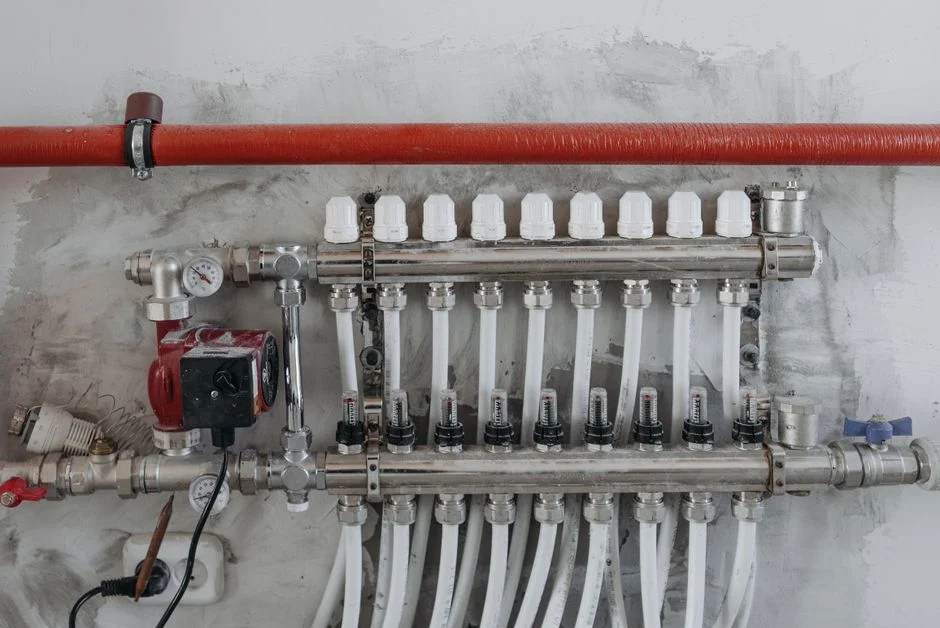
Four mixed-material failure modes account for most POU excursions. None of them are visible in the polish loop's online meters; all of them show up at the dispense point.
Galvanic / dissimilar-metal couples. Any brass valve body, zinc-plated carbon-steel clamp, or lower-grade stainless in series with 316L SS in the POU creates a galvanic couple that leaches Cu, Zn, and Fe into the water. Trace metals depress resistivity and poison gate stacks. The classic failure pattern is a 316L SS polish loop, a brass-bodied needle valve at the dispense manifold, and a slow Cu drift that the central loop's online meters do not see because the dispense branch tees off after the last sample port. Wikipedia (Ultrapure water) flags "particles from the walls of the fluid handling system" as a primary source — that is mixed-metal particulate corrosion in plain language.
Glass and glass-filled polymers. Silica is a controlled sub-ppb contaminant in advanced UPW. Any sight glass, glass-filled PTFE, glass-filled PVDF, or fibre-reinforced plastic fitting in the dispense path is a continuous silica source that is invisible to most online meters and is only caught by ICP-MS grabs or by a slow silica creep on a periodic lab sample. This is the most common reason a "clean" dispense path slowly drifts upward on silica.
Polymer leaching and permeability. PFA and PVDF are the practical baseline for the POU wetted path. PP and PE are more permeable to CO₂ and more prone to organic leaching, and can erase a <1 ppb TOC budget overnight. The two failure modes look the same on a TOC analyser but show up differently on a resistivity trace: a PP/PE out-gassing signature is paired with a depressed resistivity, while a leach signature is paired with a normal resistivity and a rising TOC. Engineering the POU correctly means specifying PFA or high-purity PVDF throughout, not "food-grade" or "industrial-grade" plastic.
Elastomer seals. Buna-N (NBR) and EPDM shed organics and particles, and are documented TOC contributors at dispense. FKM and FFKM (perfluorinated) are the fab-grade choices for O-rings and diaphragm seats in POU valves. The ranking FFKM > FKM > EPDM > Buna-N is the one to put on a datasheet, because every step down that list is a measurable rise in TOC and particle background.
Instrumentation tees and dead legs are the fifth, less obvious contributor. A resistivity, TOC, particle, or DO sample port adds a stainless or polymer junction of mixed grade at exactly the point the engineer does not want one. AXEON (2025) recommends placing inline monitoring at critical points in the water system; the same logic, applied to POU, means each tee has to be specified to POU standard, not loop standard, or it becomes a leach source that defeats the meter it feeds.
Material Selection Map for POU Wetted Surfaces
The map below lets a specifier walk into a vendor meeting with a class-by-class specification instead of a vague "use UPW-grade plastic". The ranking columns reflect the practical hierarchy of leachables and failure modes for the POU duty cycle.
| Wetted component class | Preferred material | Acceptable alternates | Main leachables to control | Failure mode if wrong grade is substituted |
|---|---|---|---|---|
| Tubing | High-purity PFA | High-purity PVDF where mechanical strength matters | CO₂ permeability, organic leach | TOC drift; resistivity depression; sub-ppb particle shedding |
| Manifold block | Machined PVDF or PFA-lined 316L SS | 316L SS block, EP finish, no brass internals | Trace metals (Cu, Zn, Fe), silica | Slow Cu/Zn drift; silica creep from glass-filled polymers |
| Diaphragm valve body | PFA- or PTFE-lined with FFKM diaphragm | FKM-lined as a step down | Organic leach, particle shedding at seat | TOC excursion; particle spike on each valve cycle |
| Instrument tee / sample port | PFA or high-purity PVDF body; FFKM seals | 316L SS with EP finish, no brass | Mixed-grade junction | Each tee becomes a leach source that defeats its own meter |
| Seal / O-ring | FFKM (perfluorinated) | FKM (fluorocarbon) | Organic extractables | TOC rise on every dispense cycle; particle shedding |
| End fitting / clamp / union | Same alloy as line (316L SS); no thread sealant except UPW-rated PTFE | Higher-grade SS (e.g. 316L VIM-VAR) | Mixed-alloy galvanic couple, thread sealant organics | Cu/Zn/Fe leach; TOC spike from non-UPW tape |
Three rules of thumb summarise the table. First, the polymer hierarchy is PFA > high-purity PVDF > PP/PE, and the step from PFA to PP is not a cost saving — it is a TOC budget loss. Second, the elastomer hierarchy is FFKM > FKM > EPDM > Buna-N, and Buna-N and EPDM have no business downstream of the final polish filter. Third, mixed-alloy unions and thread sealants are the two fittings that get installed by maintenance and almost never get re-validated; the spec has to forbid them in writing.
Designing the POU Skid and Dispense Manifold
The dispense path is sequenced as follows: polishing loop return → final POU polishing filter (≤200 nm pore per Wikipedia) → POU manifold → tool dispense, with sample ports for resistivity, TOC, particles, and DO in that order. AXEON (2025) places inline monitoring at "critical points in the water system"; for the POU, the critical point is the dispense manifold, not the loop return.
The POU skid should be laid out to avoid "T" connections that mix upstream and downstream water. Each tool cluster should be fed by a dedicated dispense line so that a single tool's excursion — typically a wet bench pulling a slug of contaminated water back through the dispense check valve — cannot contaminate neighbouring tools. The dispense check valve is itself a wetted component: it has to be PFA- or PTFE-bodied with an FFKM seal, not a brass-bodied inline check.
POU-side reject water is the other half of the design. LinkedIn (Kumar Priyadarshi, 2024-11) frames point-of-use wastewater segregation as a high-return opportunity, noting that separating scrubber streams lets plants add capacity without new intake permits and cuts discharge fees 15–30%. The same logic protects the polish loop from re-entrainment: segregated POU reject (scrubber, rinse, CMP) keeps fluoride, slurry, and organic loads from cycling back into the polisher. In a typical retrofit, the dispense manifold's reject line hands off to a side-stream polishing train that can include point-of-use polishing UF, EDI polishing modules upstream of POU, and a POU-side UV steriliser for TOC trim. Membranes and filter elements along the same train should be specified to the same POU standard; POU-grade replacement membranes and filter elements are the items most often quietly downgraded during a maintenance cycle.
A useful pre-build checklist: (1) every wetted surface in the P&ID from the polish filter to the tool is on the materials map; (2) no brass, Buna-N, EPDM, PP, or PE appears downstream of the polish filter; (3) every instrument tee is PFA-bodied with FFKM seals; (4) the reject line is segregated by stream and metered; (5) the dispense check valve is all-polymer with FFKM. A cross-reference to the wider fab-side water cycle is useful at the design stage — the third-generation semiconductor wastewater ZLD case study and the Tokyo data center cooling blowdown 2026 guide show the wider reject-stream context, and the seven root causes of wastewater treatment failure post is a useful sanity check for the failure modes the POU design is meant to avoid.
Field Troubleshooting: Tracing an Excursion Back to a Mixed-Material POU
Most POU excursions are diagnosed in the wrong place because the symptom-to-cause mapping is not written down. The map below is the one to keep on the engineer's terminal.
Slow resistivity drift, no sodium rise, normal TOC. Check polymer tubing permeability and any fitting installed in the last 30 days. CO₂ diffusion through PP/PE or a freshly installed non-UPG-rated fitting is the most common cause. A grab sample run on a high-sensitivity conductivity cell with and without a CO₂ trap on the inlet confirms it.
Sudden particle spike. Check recent fitting work, valve-seat wear, and dead-leg volume. A Buna-N or EPDM O-ring replaced during maintenance is the single most common cause. Pull the last work order and walk the dispense path.
Sodium breakthrough at POU. This is a polish-loop problem, not a POU material problem. Wikipedia (Ultrapure water) describes sodium as the leading-edge ion for cation-exchanger breakthrough. Confirm at POU and trace back to the loop; do not pull fittings.
Silica creep at POU. Strong signal of a glass, glass-filled, or fibre-reinforced component that was specified incorrectly for UPW service. Sight glasses and glass-filled PTFE seats are the usual culprits. Pull the P&ID and audit every wetted component for "glass-filled" or "fibre-reinforced" callouts.
TOC excursion that disappears overnight. Almost always biological at POU — filter, dead leg, or diaphragm — not feedwater. Consistent with Wikipedia's note that "after polishing, UPW is typically cycled continuously … to prevent stagnation". A stagnant dispense line or a dead leg downstream of a rarely used valve is the most common cause. The fix is continuous recirculation at the dispense manifold and dead-leg elimination, not a polish-loop change.
Frequently Asked Questions
What wetted materials are forbidden downstream of the final POU polishing filter?
Brass, zinc-plated carbon-steel, Buna-N (NBR), EPDM, PP, PE, and any glass-filled or fibre-reinforced polymer are the materials that have no place between the ≤200 nm final polish filter and the tool dispense. The reason is the SEMI F63 budget: brass and carbon steel drive Cu/Zn/Fe leach, Buna-N and EPDM drive TOC and particle shedding, PP and PE drive CO₂ permeability, and glass-filled polymers drive silica creep. The full replacement specification is PFA or high-purity PVDF tubing, PFA- or PTFE-lined 316L SS manifolds, FFKM (or at minimum FKM) seals, and 316L SS end fittings with no thread sealant other than UPW-rated PTFE tape.
What is the POU-side particle target for sub-7 nm, and how is it verified?
The SEMI F63 target is <0.3 particles/mL above 0.05 µm, measured by a laser particle counter at the dispense manifold (AXEON, 2025). Wikipedia (Ultrapure water) tightens this through the "half-feature-size" rule: all particles above one-half of the smallest feature must be removed, so a sub-7 nm logic fab is targeting particles above roughly 3 nm — well below the 0.05 µm counter channel. The practical implication is that the 0.05 µm counter is the floor of online verification, not the ceiling. Material specification (no mixed-metal couples, no shedding elastomers, no glass-filled polymers) is what protects the sub-counter budget.
How do I budget and justify a POU retrofit to a mixed-material-free dispense path?
Use the LinkedIn (2024-11) POU-wastewater-segregation benchmark — 15–30% reduction in discharge fees from separating scrubber streams — and pair it with the yield cost of a sub-7 nm excursion that the polish loop cannot catch. The retrofit itself is dominated by replacement of brass manifolds, Buna-N/EPDM seals, and PP/PE tubing, not by new polishers. Request vendor itemised pricing per dispense branch and per fitting class; do not accept a single lump-sum number, because the cost driver is the number of mixed-material fittings in the existing path, which a walk-down will reveal in an hour.
How do I audit a vendor's POU skid for material compliance before acceptance?
Request the bill of materials restricted to wetted components, with material grade and standards callout (UNS S31603 for 316L SS, FFKM/FKM grade number, PFA/PVDF resin grade and manufacturer). Reject any line item that does not name a specific resin or alloy grade. Confirm that no instrument tee, sample port, or check valve downstream of the final polish filter contains brass, Buna-N, EPDM, PP, PE, or glass-filled polymer. Require a documented FAT protocol that includes a 24-hour recirculation rinse with end-of-line resistivity, TOC, and particle data; this is the only FAT that actually proves mixed-material leaching is under control. The acceptance criteria the buyer should put in writing are TOC <1 ppb (or <0.5 ppb at sub-7 nm), resistivity >18.2 MΩ·cm at 25 °C, and <0.3 particles/mL above 0.05 µm at the dispense outlet after the rinse.