
What a Coarse Bar Screen Does in a Wastewater Headworks
A coarse bar screen is a mechanical screening device placed at the headworks of a wastewater treatment plant to capture large debris before it reaches pumps and downstream processes. In the standard classification used by Eng—Advances in Engineering (2025), coarse screens are defined as bar screens with clear openings between 6 mm and 150 mm, while fine screens have clear spacings below 6 mm. Industrial coarse bar screens sold for pumping stations, WWTP inlets and power plant intakes, such as the HUBER Coarse Screen TrashMax, specify cleaning rakes that lift captured solids off the bars and discharge them to a screenings handling unit, with the primary function being protection of downstream equipment rather than solids removal to discharge quality.
At the headworks, the coarse bar screen is the first engineered barrier between the collection system and the rest of the plant. It intercepts rags, plastics, wood, bricks, and other large objects that would otherwise lodge in pump impellers, clog valves, blind aeration diffusers, and upset biological processes. The screen is sized so the bulk of nuisance material is removed mechanically, leaving only the smaller particles to be handled by grit removal, primary clarification, and biological treatment further downstream. This is why headworks screening sits ahead of grit chambers and primary tanks in the process flow diagram: removing the coarse fraction first protects every unit operation that follows.
A coarse bar screen captures debris on the surface of a fixed bar rack by size exclusion, whereas a comminutor or grinder size-reduces the same debris and returns it to the flow. Removal produces a screenings fraction that must be conveyed, washed, dewatered, and disposed of; size reduction keeps solids in the process stream but adds a maintenance-intensive device upstream of the screen. For most municipal and industrial headworks in 2026, capture-and-remove remains the default because it directly protects pumps and downstream equipment without re-introducing shredded material into biological stages.
Typical placement matches the use cases published for the HUBER Coarse Screen TrashMax: at pumping stations to protect the wet well and pumps, at the first stage of municipal WWTPs, at industrial plant inlets, and at power plant cooling-water intakes. In each case the bar rack is installed vertically or near-vertically in a concrete channel, and a cleaning mechanism lifts captured material out of the flow for disposal.
Coarse vs Fine Screen: How the Choice Is Made
The 6 mm clear-opening threshold is the dividing line that recent CFD literature uses to separate coarse from fine screening. Above 6 mm and up to 150 mm, screens are classified as coarse and are used to remove heavy, bulky debris; below 6 mm, fine screens handle rags, wipes, and fine plastics. The same Eng (2025) CFD simulation shows that a 10 mm particle approaching a 6 mm bar gap is retained at nearly 100%, so any debris larger than the opening is captured reliably on the bar rack; smaller particles fall through to be addressed by a fine screen or by downstream treatment stages.
Density matters as well. The Eng (2025) study notes that higher-density particles are more easily trapped by the bars, while buoyant and low-density material can be pushed through the opening by the velocity field. This is one reason pre-grit removal or a flow-conditioning baffle is sometimes placed ahead of the bar rack when the influent carries a high grit load.
Match screen class to downstream sensitivity. A primary-only works with a coarse screen alone if the headworks goal is pump and valve protection. A plant feeding an MBR or UF membrane needs a fine screen ahead of the membranes to control carryover, because membrane systems tolerate very little fibrous or plastic debris. In practice, many plants run a coarse bar screen at 12–25 mm followed by a fine screen at 2–6 mm to share the load.
Duperon's product documentation draws the same line in inches: coarse screens with openings from ½ inch to 4 inches (≈12.7–100 mm) for protection duty, and fine screens with openings from 0.125 inch to 0.5 inch (≈3.2–12.7 mm) for polishing duty. The two bands overlap with the metric 6 mm threshold once unit conversion is applied, which is why most specifiers will see coarse-screen offerings quoted in inches and fine screens quoted in millimetres or fractional inches.
| Parameter | Coarse bar screen | Fine screen |
|---|---|---|
| Clear opening (metric, per Eng 2025) | 6 mm to 150 mm | < 6 mm |
| Clear opening (Duperon commercial range) | ½ in to 4 in (≈12.7–100 mm) | 0.125 in to 0.5 in (≈3.2–12.7 mm) |
| Primary function | Pump and downstream equipment protection | Polishing; reduce carryover to biological/membrane stages |
| Typical target debris | Rags, wood, plastics, bricks, bulky solids | Wipes, fine plastics, fibres |
| Retention of 10 mm particle against 6 mm opening (Eng 2025) | ≈100% | Not applicable (no bar rack at this size) |
Key Design Parameters: Opening, Bar Shape, Channel and Approach Velocity
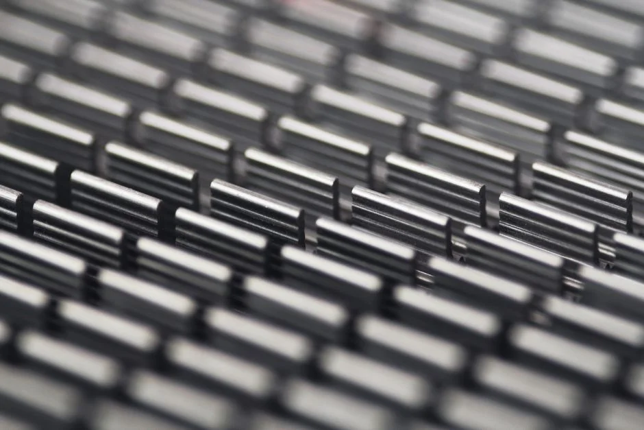
Opening size is the first design choice and is governed by what the screen is meant to protect. The Eng (2025) study covers the full 6–150 mm coarse band; commercial coarse screens from Duperon cluster at 12.7–100 mm (½–4 in) for typical protection duty. The opening should be smaller than the tightest downstream pump impeller passage and should be selected with the screenings handling capacity of the plant in mind, because wider openings pass more debris but reduce the screenings load on the disposal system.
Bar cross-section has a measurable effect on both head loss and small-particle capture. In the Eng (2025) CFD work, the rectangular bar shape produced the highest upstream pressure of the four profiles tested, while the streamlined shape produced the lowest upstream pressure. The same study reports that the rectangular cross-section retains roughly 10% more 2 mm particles than rounded or teardrop shapes. The trade-off is therefore explicit: specify rectangular bars for maximum small-particle capture at the cost of higher head loss, or specify streamlined bars when the head-loss budget is tight and a downstream fine screen will catch the 2 mm fraction.
Channel geometry sets the hydraulic boundary conditions for the bar rack. The Eng (2025) model used a rectangular channel 1.2 m deep, 3 m long, and 0.8 m wide, with two 105 mm × 5 mm side sealing blades on the bar screen to prevent bypass along the walls. The sealing blades matter because free surface flow along the bar screen sides creates pressure deviation and lets debris pass; the blades mitigate this and should be specified for any equivalent full-scale unit installed in a comparable rectangular channel.
Approach velocity must be high enough to keep debris moving into the bars and to scour the channel, but not so high that head loss across the rack becomes excessive or that the bar rack blinds with rags. The Eng (2025) reference notes that lower inlet velocity causes deposition of solid debris in the upstream screening channel and degrades performance, which is why the channel cross-section is sized against the design peak flow rather than the average flow. A common engineering input is the velocity at the bar rack face, which the specifier should calculate from design flow divided by the wetted channel area at the rack and then check against the value used in the supplier's head-loss curve.
Head loss is the operational consequence of every choice above. Rectangular bars give the highest pressure drop; streamlined bars give the lowest. Side sealing reduces losses associated with wall bypass but does not change the bar-shape loss term. The specifier should request a head-loss curve from the supplier plotted as a function of approach velocity and blinded-bar fraction, then size the channel so peak wet-weather head loss stays inside the plant's hydraulic profile. Operating links to the broader DAF plant operation and maintenance guide downstream of screening often sit close to the available head, so leaving margin at the bar rack is worth the channel cost.
| Parameter | Range / value from research | Source |
|---|---|---|
| Coarse opening band | 6 mm to 150 mm | Eng (2025) |
| Typical industrial coarse opening | ½ in to 4 in (≈12.7–100 mm) | Duperon product line |
| Reference channel geometry (Eng 2025) | 1.2 m deep × 3 m long × 0.8 m wide | Eng (2025) |
| Side sealing blade dimensions | 105 mm wide × 5 mm thick | Eng (2025) |
| 2 mm particle retention: rectangular vs rounded/teardrop bars | Rectangular ≈10% higher | Eng (2025) |
| Relative upstream pressure by bar shape | Rectangular highest; streamlined lowest | Eng (2025) |
| Retention of 10 mm particle against 6 mm opening | ≈100% | Eng (2025) |
Cleaning Mechanisms: Manual, Catwalk/Cable-Rake, Chain-Rake and Rotary
Manual raking is the baseline. It is acceptable for very small flows, for installations serving remote or unmanned sites, or as a backup to a mechanical system that may be down for service. Manual rakes are inexpensive to install but expose operators to confined-space and falls hazards and do not provide continuous screening at peak flow, which is why most WWTPs above about 1 MLD average flow have moved to mechanical cleaning.
Cable-operated coarse screens use chain- or cable-driven rakes that travel up the bar rack and discharge screenings at the top. The HUBER TrashMax, for example, drives both ends of each cleaning rake from robust drive chains, with sprockets on a common shaft turned by a gear motor. Each rake is guided by two wear-resistant rollers running in lateral guide tracks so the rake stays engaged with the bar rack through the full lift. The rakes engage the bar rack at the bottom dead centre, cleaning the rear of the rack first and then the front, which prevents material accumulation in front of the screen. This sequenced lift is a useful point to include in a specification: the specifier should ask the supplier to describe the rake path and confirm that debris is not pushed back into the flow on the upstroke.
Chain-rake coarse screens use multiple rakes fixed to one or two endless chains, similar in principle to the cable-driven systems but with rigid chain links rather than cables. Multi-rake designs are preferred for high-solids loading because the number of rakes and the chain speed together set the discharge capacity, and VFD-controlled drives let the operator tune capacity to load conditions. The HUBER Multi-Rake Bar Screen RakeMax and RakeMax CF are cited by the manufacturer as comparable multi-rake options for installations that need compact footprint with high discharge rates.
Rotary mechanical bar screens, such as the HydropureWater rotary mechanical bar screen, use a rotating element with rake teeth that engage the bar rack continuously. They are well suited to fine screening duty on channels with a self-cleaning brush discharge and dual overload protection, and are typically applied where the operator wants continuous automated cleaning without the rake-lift mechanism of a chain or cable system. The selection of cleaning mechanism is therefore driven by opening size, channel depth, debris load, and the level of automation required.
| Mechanism | Typical application | Drive and control | Notes from research |
|---|---|---|---|
| Manual rake | Very small flows, unmanned sites, backup | Operator | Baseline against which mechanical options are justified |
| Cable-operated (e.g. HUBER TrashMax) | Pumping stations, WWTP inlets, power plant intakes | Gear motor on common shaft; dual drive chains; rollers in lateral tracks | Rakes engage at bottom dead centre, clean rear then front to prevent material build-up |
| Chain-rake (multi-rake) | High-solids, deep channels | VFD-controlled; multiple rakes per chain | Discharge capacity scales with rake count and speed |
| Rotary mechanical | Continuous-duty fine screening, headworks protection | Continuous rotation; self-cleaning brush discharge | Suited to channels with self-cleaning brush discharge and dual overload protection |
Selection Framework: Matching Screen to Debris, Flow and Downstream Risk
Use the following five-step process when converting the technical detail above into a specific equipment choice for a plant.
- Characterise the debris. Bulky and buoyant material (wood, large plastics, rags) at high loading calls for a coarse screen with an opening ≥25 mm and a multi-rake cleaning mechanism. Fibrous and wipe-heavy influent, including material from healthcare and long-term-care facilities, needs a fine screen downstream of the coarse screen.
- Size the opening against downstream clearance. The opening must be smaller than the pump impeller passage and smaller than the clearances in any downstream valves or fine screens. For MBR or UF plants, set the maximum carryover limit (typically a particle size) and work backward to the fine-screen opening, then confirm the coarse screen upstream is sized to keep the fine screen from blinding.
- Check approach velocity against channel area. Calculate the velocity at peak wet-weather flow. If the velocity is too low, debris will deposit upstream of the bar rack as flagged by the Eng (2025) reference; if it is too high, the rack will blind. Resize the channel cross-section or add a flow-splitting baffle before committing to the bar rack.
- Select the cleaning mechanism by debris load. High-bulky loads need multi-rake chain or cable systems with VFD-driven discharge. Low-load sites or narrow channels can use single-rake catwalk units. Rotary units are appropriate for continuous-duty fine screening on smaller channels.
- Specify bar cross-section with the head-loss budget in mind. Choose rectangular bars for maximum small-particle capture when head loss is not the limiting constraint; choose streamlined bars when head loss is constrained and a downstream fine screen will handle the small-particle fraction.
Failure modes for coarse bar screens cluster around three issues: blinding from rags and wipes, rake jamming from oversized debris, and side bypass where wall sealing is inadequate. These are the same failure families that drive the common failure modes in wet processing equipment, and the prevention measures (rake overload trips, side sealing blades, and a defined screenings handling capacity upstream of the disposal unit) apply directly. The specifier should ask each bidder to address each failure mode in writing and to supply the relevant setpoints.
Frequently Asked Questions
What clear opening defines a coarse bar screen in 2026?
Coarse bar screens cover clear openings from 6 mm to 150 mm per the Eng (2025) classification. Commercial coarse offerings such as Duperon's coarse line cluster at 12.7–100 mm (½–4 in) for typical protection duty. Any bar screen with a clear opening below 6 mm is classified as a fine screen.
How does the opening choice interact with downstream pump and membrane clearance?
The opening must be smaller than the smallest pump impeller passage the screen is meant to protect, and small enough to keep fibrous carryover below the limit the downstream biological or membrane stage can tolerate. For MBR and UF plants, the binding constraint is usually the membrane tolerance rather than the pump clearance, which is why a coarse-fine screen pair is standard at those sites.
Which cleaning mechanism should I specify for a high-solids influent?
For high-solids duty, specify a multi-rake chain or cable-operated screen with VFD-driven discharge so the number of rakes and the discharge speed can be tuned to the load. For low-load or narrow-channel sites, single-rake catwalk units or rotary mechanical screens are sufficient and lower in capital cost. The supplier's reference list at comparable plants is the practical check on the right choice.
What should I include in an RFQ to control lead time and configuration risk?
Ask bidders to confirm the manufacturing lead time for the configured opening size, channel dimensions, and rake count in writing; to provide a head-loss curve at the design approach velocity with a defined blinded-bar fraction; to list the side-sealing arrangement and the rake overload protection setpoints; and to state the country of origin for the drive train, chains, and rake wear parts. The absence of a confirmed lead time for the configured opening and rake count is a common cause of programme slip, so the RFQ should require it as a pass/fail line item rather than as a comment.