Why Odor Complaints Are a Corrosion Warning Sign
Hydrogen sulfide is the dominant odorant and corrosion agent in sanitary sewerage; it is detectable at very low concentrations and is toxic (EPA Design Manual, 1985, Chapter 1). The same sulfide chemistry that creates odor attacks steel tanks, concrete, and metal pipelines used in conventional primary, secondary, and tertiary treatment (Khamis, Reyad & Abd-El-Khalek, 2025, npj Materials Degradation, 9:95, Introduction). NACE estimates the global cost of corrosion at approximately US$2.5 trillion, or about 3.5% of global GDP (Koch et al., 2016, cited in Khamis et al., 2025). National-scale repair backlogs illustrate the same pattern in water and sewer infrastructure: Australia estimates AUD 125 billion over 20 years for water and sewer pipeline repairs, and New Zealand estimates AUD 25 billion (Melchers & Tan, 2022; Bender et al., 2022, cited in Khamis et al., 2025).
For an industrial plant, a recurring odor complaint from a lift station, headworks, or force main is a corrosion data point, not a public-relations problem. The same biofilm activity that releases H₂S into the air is consuming pipe wall simultaneously. Odor is what the operator notices; corrosion is what the budget eventually pays for.
How Hydrogen Sulfide Forms and Attacks Infrastructure
Sulfate-reducing bacteria generate sulfide under anaerobic conditions in force mains, lift stations, and treatment units (EPA Design Manual, 1985, Chapter 2; Khamis et al., 2025, Corrosion section). The pH of the wastewater determines the proportion of dissolved H₂S versus HS⁻ ion, which controls both odor release and the rate of corrosion flux to pipe walls (EPA Design Manual, 1985, Section 2.2, Figures 2-2 and 2-3). Below pH 7, dissolved H₂S dominates and off-gases readily; above pH 8, the HS⁻ ion predominates and stays in solution, shifting the attack from the surrounding air to the pipe wall.
Seven recognized corrosion types affect wastewater systems: uniform, galvanic, pitting, crevice, intergranular, stress corrosion cracking, and microbially influenced corrosion (MIC) (Khamis et al., 2025, Corrosion section). MIC is mechanistically distinct from inorganic forms because it requires three components — electrolyte, metal, and microorganisms — and proceeds when microbes secrete extracellular polymeric substances that form biofilms on the metal surface, initiating localized attack (Khamis et al., 2025, citing Ram, Zaman & Dhir, 2019). Industrial wastewater contributes acids, alkalies, organic compounds, and heavy metals that accelerate all seven corrosion types once they enter a municipal or industrial collection system (Khamis et al., 2025, Introduction; Srivastava et al., 2020, cited therein).
Pipeline Condition Assessment: Direct vs. Indirect Techniques
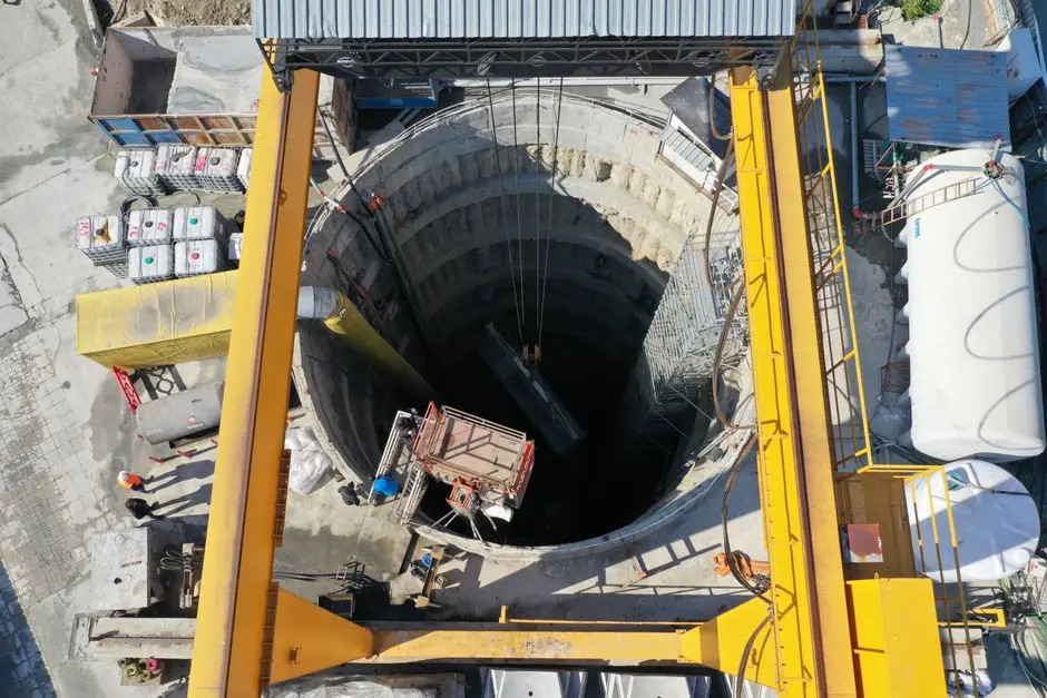
Standard pipeline assessment relies on direct inspection (visual, ultrasonic, coupon retrieval) and electrical methods tied to cathodic protection continuity. For electrically discontinuous buried water and wastewater pipelines, standard electrical survey techniques cannot be applied across the full run, necessitating indirect condition assessment techniques such as remote field eddy current, close-interval potential surveys with isolated segments, and acoustic emission (NACE International, case study on indirect assessment of electrically discontinuous buried pipelines, 2018). This configuration is common at older industrial sites where pipe segments were joined with non-conductive couplings or where repair clamps break electrical continuity.
A monitoring program should characterize severity (corrosion rate, pit depth growth) and locate hotspots where sulfide flux to the pipe wall is highest — typically long flat sections, low-velocity force mains, and downstream of pump stations (EPA Design Manual, 1985, Sections 2.6–2.7). Assessment frequency should be risk-based: high-sulfide force mains and treatment plant headworks warrant more frequent inspection than gravity interceptors in well-ventilated systems. Specify assessment scope by unit process — preliminary, primary, secondary, and tertiary stages each present different corrosion and odor exposure profiles (Khamis et al., 2025, Corrosion in municipal wastewater section; EPA Design Manual, 1985, Chapter 6).
| Pipeline Configuration | Preferred Assessment Method | Typical Use Case |
|---|---|---|
| Electrically continuous buried line with active CP | Close-interval potential survey, coupon retrieval, ultrasonic UT | Newer steel force main with bonded joints and impressed-current system |
| Electrically discontinuous buried line | Indirect: remote field eddy current, acoustic emission, isolated-segment potential surveys | Older line with non-conductive couplings, repair clamps, or dielectric joints |
| Accessible gravity interceptor | Visual + man-entry coupon, pH/ sulfide profiling at manholes | Well-ventilated gravity sewer with low sulfide risk |
| High-sulfide force main, no entry | Insertion probes, sulfide flux coupons, hydraulic model + sulfide prediction | Long flat force main downstream of pump station |
Matching Corrosion Type to Control Strategy
Uniform corrosion across metal surfaces responds to material upgrades and protective coatings. In synthetic wastewater testing, stainless steel showed no localized corrosion, while 1018 carbon steel showed minor localized attack (Sandoval-Jabalera et al., 2006, cited in Khamis et al., 2025). MIC-driven pitting requires biofilm control, not just chemical oxidation: nitrate dosing can suppress sulfate-reducing bacteria by providing a more favorable electron acceptor, as documented in the EPA Design Manual at the Bluff Cove force main in Los Angeles (EPA Design Manual, 1985, Figure 3-27) and in activated-carbon column trials (Table 4-3).
Localized pitting in H₂S-containing wet atmospheres is documented in lean duplex stainless steels at higher H₂S concentrations, indicating material limits even for corrosion-resistant alloys and the necessity to control H₂S concentration rather than rely on alloy upgrade alone (Larché et al., 2021, cited in Khamis et al., 2025). Crevice corrosion under gaskets, bolts, and deposits requires design changes — joint selection, elimination of stagnant zones — rather than chemical dosing alone (Khamis et al., 2025, Corrosion section). Galvanic corrosion from dissimilar metals in contact needs isolation via dielectric unions or a material compatibility review, not chemical treatment (Khamis et al., 2025, Corrosion section).
Industrial Water Solutions: Equipment and Chemical Control Technologies
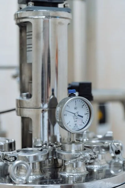
Chemical oxidation is the most established sulfide-control approach: chlorine, hydrogen peroxide, and potassium permanganate are documented in the EPA Design Manual with typical dosing configurations and case histories (EPA Design Manual, 1985, Sections 3.3 and 4.3). Hydrogen peroxide is widely used for sulfide control in force mains and at treatment plant headworks, with case histories in Palm Beach County, FL and Baltimore, MD (EPA Design Manual, 1985, Section 3.4 and Table 4-1). Sodium nitrate addition suppresses sulfide generation biologically and is documented at the Bluff Cove force main in Los Angeles (EPA Design Manual, 1985, Figure 3-27). Forced-draft ventilation and air-injection systems (U-tubes, direct air/oxygen injection) maintain aerobic conditions in force mains to prevent sulfide formation; documented installations include Jefferson Parish, LA; Port Arthur, TX; Sacramento, CA; and Westville, NJ (EPA Design Manual, 1985, Section 3.2, Tables 3-2 through 3-5 and 3-23).
For sites where residual chlorine is undesirable — cooling loops, process-water reuse, food and pharma effluent — on-site generated chlorine dioxide provides oxidation capacity for both disinfection and sulfide control, with documented configurations spanning 50 g/h to 20,000 g/h. An on-site chlorine dioxide generator sized to the measured sulfide load avoids the transportation, storage, and neutralization liabilities of bulk oxidant deliveries. Reliable dosing at industrial scale requires a PLC-controlled chemical dosing skid that can hold oxidizer, pH adjuster, and specialty biocide setpoints under varying flow. For background on the broader control loop, the 2026 engineering guide to auto dosing for wastewater walks through control architecture, and discharge-bound sites can cross-check the chosen chemistry against the 2026 petrochemical wastewater discharge compliance guide before procurement.
| Control Technology | Primary Mechanism | Best-Fit Problem | Documented Reference |
|---|---|---|---|
| Air / oxygen injection (U-tube, direct) | Maintains aerobic conditions, prevents SRB activity | Long force mains, flat grades, downstream of pump stations | EPA Design Manual 1985, Tables 3-2 to 3-5, 3-23 (Jefferson Parish LA, Port Arthur TX, Sacramento CA, Westville NJ) |
| Hydrogen peroxide (H₂O₂) dosing | Direct oxidation of dissolved sulfide | Force main sulfide control, headworks odor peaks | EPA Design Manual 1985, Section 3.4, Table 4-1 (Palm Beach County FL, Baltimore MD) |
| Sodium nitrate addition | Provides alternative electron acceptor, suppresses SRB | MIC-driven pitting, biofilm-dominated force mains | EPA Design Manual 1985, Figure 3-27 (Bluff Cove, Los Angeles CA); Table 4-3 |
| Chlorine / hypochlorite | Oxidation of sulfide to sulfate | Treatment plant headworks, wet scrubbers | EPA Design Manual 1985, Tables 3-13, 3-14, 3-15 (Sacramento CA, Tampa FL) |
| On-site chlorine dioxide generation | Selective oxidation, lower halogenated byproducts than Cl₂ | Cooling loops, process wastewater, sites avoiding residual chlorine | Manufacturer configurations 50 g/h to 20,000 g/h |
| Material upgrade + protective coating | Reduces susceptibility to uniform / pitting attack | Replacement of 1018 carbon steel components | Sandoval-Jabalera et al. 2006, cited in Khamis et al. 2025 |
Frequently Asked Questions
What budget range should we plan for an industrial wastewater odor and corrosion control project in 2026?
The EPA Design Manual (1985) documents cost ranges for individual control technologies — air injection, chlorination, hydrogen peroxide, wet scrubbers, ozone, and thermal or catalytic incinerators — across Tables 3-7, 3-12, 3-16, 3-19, 4-6, 4-10, 4-12, 4-13, and 4-15; however, these figures are historical and require adjustment. Request itemized vendor quotations tied to the specific unit process identified in your assessment (force main sulfide load, headworks H₂S peak, MIC severity) and your required sulfide removal efficiency, escalating against current chemical and stainless-steel index prices.
How do we select a supplier for pipeline assessment and corrosion control equipment?
Match the supplier's documented capability to the diagnosed problem rather than the equipment catalog. For electrically discontinuous buried lines, require evidence of indirect assessment experience — remote field eddy current, acoustic emission, or isolated-segment potential surveys — as described in the NACE case study (2018). For chemical control, require case histories at similar hydraulic retention time, sulfide loading, and effluent toxicity constraints, and confirm the dosing skid integrates with your existing PLC and instrumentation.
How often should pipeline condition assessment be repeated once a baseline is established?
Frequency should be risk-based rather than calendar-based. High-sulfide force mains, treatment plant headworks, and downstream-of-pump-station sections carry the highest corrosion flux and warrant more frequent inspection than well-ventilated gravity interceptors (EPA Design Manual, 1985, Sections 2.6–2.7). The first re-assessment interval should be set against the measured corrosion rate and pit-depth growth from the baseline, then adjusted as control measures take effect.
What is the main compliance risk if we leave odor and corrosion unaddressed?
Two layers of risk sit on top of the asset-integrity cost. First, atmospheric H₂S at the headworks and in collection systems is a documented toxic exposure hazard to operators and surrounding communities (EPA Design Manual, 1985, Section 2.8). Second, the corrosion mechanisms described in the npj Materials Degradation review (Khamis et al., 2025) — uniform, pitting, MIC, crevice,