Why Industrial Plants Add Activated Carbon to COD Treatment Trains
Granular activated carbon (GAC) is positioned by the EPA as an advanced (tertiary) treatment step that follows primary sedimentation or biological stages, not as a standalone primary COD remover (EPA 832-F-00-017, September 2000). Each carbon bed performs three functions at once: chemical adsorption of dissolved organics, physical filtration of suspended solids, and incidental anaerobic biological degradation within the biofilm that colonizes the carbon surface. At the MHRRF and Niagara Falls NFWTP, the EPA fact sheet explicitly credits this combined mechanism for the observed COD and solids performance, which is why operators with secondary effluent that still exceeds COD limits reach for GAC after biology, not before it.
The pilot that makes this concrete ran on Singuedala River water in Guinea, where GAC produced from peanut shells and chemically activated with 35% sulfuric acid delivered 40.85% COD reduction in the first filter pass and 64.44% after the second pass (Green and Sustainable Chemistry, 2023). The single-pass result mirrors the operating reality at MHRRF, where post-regeneration COD removal is documented at roughly 50% and drops to about 25% as the bed exhausts (EPA 832-F-00-017). Engineers should read those numbers as an envelope, not a guarantee: a fresh GAC bed at proper contact time sits near the upper end, and an exhausted or undersized bed sits at the lower end.
Another reason carbon sits at the polishing position is measurement. COD is used as the surrogate for non-biodegradable organic removal in GAC columns because BOD progressively underestimates total organics as refractory compounds dominate the residual (EPA 832-F-00-017). For plants evaluating whether their post-biological COD is "refractory or just undertreated," this framing is the decision pivot, and it is covered in more depth in the broader 2026 COD and suspended-solids removal guide.
How GAC Actually Removes COD: Adsorption Plus Incidental Biodegradation
Adsorption is the primary COD removal mechanism. Organic molecules migrate from solution and adhere to the internal walls of the pore network inside each carbon particle; the network is created by thermal activation of carbonaceous precursors, and the resulting internal surface area can exceed 1,500 m² per gram of carbon (EPA 832-F-00-017; Green and Sustainable Chemistry, 2023). That surface area is the reason a cubic meter of packed GAC can out-perform a much larger volume of less porous media, and it is the parameter a buyer should demand from any media datasheet.
The second mechanism is incidental biodegradation. A GAC bed is not sterile: anaerobic biomass colonizes the pore surfaces and slowly consumes a fraction of the adsorbed organics, regenerating some adsorption capacity in place. The EPA fact sheet attributes part of the MHRRF and Niagara Falls performance to this incidental activity alongside the chemical adsorption (EPA 832-F-00-017). For engineers, the practical consequence is that a fresh bed and a biologically mature bed can deliver different COD numbers on the same feed, and that biofilm growth must be planned for in backwash and surface-wash cycles.
Carbon can be manufactured from a wide range of precursors: bituminous coal, coconut shell, and agricultural wastes such as peanut shells. The Singuedala pilot activated peanut-shell char with 35% sulfuric acid and still produced a working GAC, demonstrating that the adsorption mechanism is not tied to a single feedstock (Green and Sustainable Chemistry, 2023). What is shared across feedstocks is the finite number of adsorption sites, and once those sites are occupied the bed exhausts. The EPA fact sheet quantifies the resulting performance drop from roughly 50% COD removal at fresh/regenerated conditions to about 25% as the GAC ages (EPA 832-F-00-017), and that range is the working envelope for any GAC polishing design.
Contactor Design: Fixed Bed, Expanded Bed, and Moving Bed Systems

Three contactor geometries dominate industrial GAC practice, and the choice is driven by feed solids, flow variability, and how the plant intends to handle spent carbon. The EPA fact sheet describes each and gives the full-scale dimensions engineers need for budget sizing (EPA 832-F-00-017, September 2000).
Downflow fixed-bed contactors are the most common: a lined steel column or a steel or concrete rectangular tank holding the carbon, with wastewater applied at the top, withdrawn at the bottom through an underdrain, and provisions for backwash and surface wash to control headloss buildup and prevent surface clogging. Upflow expanded-bed contactors feed wastewater from the bottom and intentionally expand the bed like a backwash, which sheds captured solids and tolerates higher feed-solids loads. Moving-bed contactors remove spent carbon continuously, so headloss never accumulates; the carbon is transferred hydraulically as a slurry using water, compressed air, centrifugal or diaphragm pumps, or eductors. All three geometries can be operated under pressure or gravity.
| Contactor type | Flow direction | Best suited to | Reference dimensions (EPA 832-F-00-017) |
|---|---|---|---|
| Downflow fixed bed | Top to bottom through underdrain | Low-solids polished feeds, predictable hydraulic load | Niagara Falls NFWTP: 28 beds, 17.3 ft × 42 ft |
| Upflow expanded bed | Bottom to top, bed fluidizes | Higher-solids feeds; self-shedding of captured solids | MHRRF: 32 columns, 10 ft diameter × 40 ft tall |
| Moving bed | Continuous carbon exchange | Sites that cannot tolerate headloss cycling or downtime for spent-carbon removal | No reference plant cited in EPA fact sheet |
A sizing rule common to all three: the number of contactors must be sufficient to maintain effluent quality while one column is offline for spent-carbon removal or maintenance (EPA 832-F-00-017). A single-train design with no redundancy is a common procurement error, because regeneration cycles are not optional. For plants with variable influent, a multi-media filter for carbon bed pre-treatment is the typical upstream guard against premature surface blinding.
GAC vs PAC: Choosing the Right Carbon Format for COD Duty
The format choice is not cosmetic; it changes the operating model. GAC is held in fixed, expanded, or moving beds and is regenerated when exhausted, while PAC is dosed as a slurry, contacted once with the wastewater, and typically not recovered for COD service (EPA 832-F-00-017). That difference sets capital, labor, and waste-handling expectations before any adsorption calculation is done.
The Singuedala and Mamouwol pilots, both run on Guinea river water with GAC and PAC prepared from peanut shells, are the rare same-study comparison. On Singuedala, GAC delivered 40.85% COD reduction after the first filter and 64.44% after the second; on the comparable Mamouwol feed, PAC delivered higher reductions on turbidity (66.89% and 80.81% vs 25.97% and 71.01% for GAC) and on pH, but the GAC numbers on COD and BOD5 are the ones an industrial reader should focus on (Green and Sustainable Chemistry, 2023). The takeaway is that format choice depends on the target pollutant: GAC for sustained COD polishing, PAC for shock-load turbidity and color control where the carbon exits with the sludge.
| Parameter | Granular activated carbon (GAC) | Powdered activated carbon (PAC) |
|---|---|---|
| Reactor form | Fixed, expanded, or moving bed | Slurry dosed into contact basin or inline |
| COD reduction, same-study pilot | 40.85% (1st filter), 64.44% (2nd filter), Singuedala | Higher turbidity/pH reductions on Mamouwol, comparable COD not separately reported in the cited study |
| Regeneration | Thermal reactivation, on- or off-site | Typically not regenerated for COD service; discharged with sludge |
| Typical fit | Continuous polishing, regeneration logistics in place | Seasonal or shock-load treatment, simple dose-and-discharge |
| Headloss management | Backwash / surface wash or continuous exchange | Not applicable |
Under-sized GAC beds behave like an exhausted bed and deliver the ~25% residual COD removal the EPA observed at end-of-cycle (EPA 832-F-00-017), so empty bed contact time (EBCT) and the number of parallel contactors are the design levers that convert intrinsic surface area into real COD removal. Plants that cannot commit to a regeneration contract should plan the slurry-handling side of the spare-carbon problem first, using components sized for the carbon format they actually choose, including bulk activated carbon media and slurry-handling valves specified for the duty.
Operating Performance: Real COD Numbers from Operating Plants
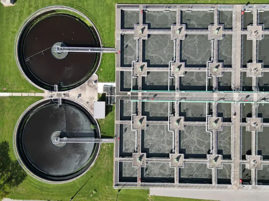
The two anchor data points for industrial GAC COD performance both come from the EPA fact sheet. At the MHRRF (Maximum Headworks Research and Rehabilitation Facility), the 32 upflow carbon columns described in the previous section deliver effluent COD of 6–7 mg/L after regeneration, corresponding to roughly 50% COD removal; the fact sheet, citing WEFTEC 1996, states that this percentage declines to about 25% as the carbon in the columns exhausts (EPA 832-F-00-017, September 2000). Post-GAC filtration at MHRRF is also what keeps the VPDES turbidity permit at 0.5 NTU, which matters for plants pairing GAC with a downstream membrane or reuse step.
The Singuedala pilot provides the staged-filtration picture. GAC cut COD by 40.85% in the first filter and 64.44% in the second, BOD5 by 31.30% and 40.87%, suspended solids by 28.97% and 76.75%, and turbidity by 25.97% and 71.01% (Green and Sustainable Chemistry, 2023). The step from the first to the second filter is the empirical justification for two-stage GAC trains on tight industrial limits. The Niagara Falls NFWTP at 48 mgd, described in the EPA fact sheet as the largest municipal physical-chemical activated carbon wastewater plant in the United States, is the high-flow precedent an engineer can cite when sizing carbon trains for plant-scale flows.
Detecting Exhaustion and Planning Carbon Regeneration
The cleanest exhaustion trigger available in the cited data is the COD removal curve itself. Tracking effluent COD cycle-by-cycle, the EPA-documented decline from ~50% removal at fresh/regenerated conditions to ~25% as the GAC ages is the operator's signal that the bed is approaching breakthrough (EPA 832-F-00-017). Spent carbon is removed from the contactor when effluent quality reaches the minimum water quality standard defined for the site, which means the trigger is a permit-driven number, not an arbitrary calendar interval.
Once the carbon is spent, two regeneration paths exist. Small systems typically send spent carbon to an off-site commercial reactivation facility, which is the most economical option when carbon volumes do not justify capital equipment. Larger systems may install on-site thermal regeneration with multi-hearth or rotary kilns, accepting the capex in exchange for logistics control. In both cases, spent, regenerated, and virgin carbon are transported hydraulically as a slurry; the piping, pumps, and eductors that move that slurry should be specified alongside the contactor, and the spare parts list should reflect the carbon format chosen (water treatment parts, valves, and filter media sized for the slurry duty).
When to Choose Activated Carbon vs MBR, DAF, or RO

Carbon is rarely the right first step, and the right polishing step depends on what is left after upstream treatment. The decision framework below ties technology choice to the character of the residual COD, not to vendor preference.
- Residual COD is dominated by non-biodegradable refractory organics (dyes, surfactants, solvents, humic substances): GAC adsorption is the most direct polishing option, because biological polishing alone will not remove these compounds. The Singuedala and MHRRF results above are the evidence base for the expected removal range (EPA 832-F-00-017; Green and Sustainable Chemistry, 2023).
- Goal is simultaneous BOD/COD and TSS reduction with a smaller footprint and reuse-quality effluent: an MBR membrane bioreactor for biological COD reduction upstream of carbon couples activated sludge with submerged membranes and produces effluent suitable for downstream polishing or reuse.
- Suspended solids, FOG, or colloidal matter dominate the upstream load: a DAF system to remove FOG and colloids ahead of carbon protects the carbon bed from fouling and is a common pairing in high-COD industrial trains.
- Target is dissolved ions or trace organics at very low levels: RO polishing after carbon is the standard ultrapure train, with the carbon stage protecting the RO membrane from oxidant damage and organic fouling.
Frequently Asked Questions
What COD removal can a properly designed GAC system realistically deliver?
Post-regeneration GAC at MHRRF achieved roughly 50% COD removal with effluent COD of 6–7 mg/L, declining to about 25% as the bed aged, while a two-stage GAC pilot on river water reached 64.44% COD reduction after the second filter (EPA 832-F-00-017; Green and Sustainable Chemistry, 2023). For budgeting, treat 40–65% COD reduction across one or two GAC stages as the realistic envelope; actual project numbers depend on the specific influent and on EBCT, which a pilot must determine before procurement.
What should I confirm with a supplier before specifying a GAC contactor?
Ask for media specification (iodine number, surface area in m²/g, mesh size), the proposed EBCT and number of parallel contactors with one offline for regeneration, and whether they offer on-site thermal regeneration or only off-site reactivation, because the EPA fact sheet flags regeneration logistics as a primary cost and operability variable (EPA 832-F-00-017). Also confirm the contactor dimensions against a reference plant at similar flow; MHRRF uses 32 columns at 10 ft × 40 ft and Niagara Falls uses 28 beds at 17.3 ft × 42 ft, which are useful precedents for high-flow sizing.
When is PAC a better fit than GAC for COD duty?
PAC is the better fit when the carbon is dosed as a slurry for seasonal or shock-load treatment and discarded with the sludge, rather than regenerated. The same Guinea study that documented GAC COD reductions of 40.85% and 64.44% also reported PAC delivering higher turbidity and pH reductions on comparable river water, illustrating that format choice depends on the target pollutant rather than on carbon surface area alone (Green and Sustainable Chemistry, 2023). For sustained COD polishing with regeneration, GAC remains the standard.
How do I detect GAC exhaustion and trigger regeneration?
Track effluent COD cycle-by-cycle; the EPA-documented drop from roughly 50% to roughly 25% COD removal is the breakthrough signal, and spent carbon should be removed when effluent quality reaches the site-defined minimum water quality standard (EPA 832-F-00-017). Establishing that standard in the specification document before procurement is the cheapest way to make the regeneration decision a routine permit check rather than a judgment call under a noncompliance event.