
Why rendering wastewater is a different DAF design problem
Rendering wastewater carries fats, oils and grease, suspended protein, bone fines, and blood, and the loadings change hourly with cooker batch dumps and hot condensates rather than arriving as a steady flow. Both Kemco Systems and Clean Technology Post confirm that DAF technology is applied to remove FOG, suspended solids, BOD, COD and metals from industrial streams, and Clean Technology Post explicitly names circular, radial-flow DAF as the geometry used in slaughterhouse and rendering plants for this shock-loaded duty.
Performance targets the engineer can use as a design ceiling are the food-and-beverage values Clean Technology Post publishes—more than 95% FOG removal and a 40–60% BOD reduction before biological polishing—but these are bracket values, not guarantees, and must be confirmed by jar test or pilot on the rendering stream itself. High and variable solids loading is the single factor that pushes the design away from rectangular lamella DAF and toward a circular radial-flow DAF with a bottom scraper for grit and bone fines.
Design parameters the engineer must lock in before vendor talks
Saturator pressure is set at 4–6 bar, with packed-tower saturators reaching 80–95% air saturation efficiency (Clean Technology Post, 2026). Microbubble diameter must stay in the 10–100 µm window; too large creates turbulence and poor attachment, too small lacks lifting capacity (Clean Technology Post, 2026). The air-to-solids ratio is the primary design parameter, running 0.005–0.06 mL of air per mg of solids; rendering streams sit at the upper end of that band because FOG and protein form light flocs (Clean Technology Post, 2026). Hydraulic loading rate is 5–30 m³/m²·h, with high-rate DAF reaching up to 50 m³/m²·h using plate packs or lamella settlers (Clean Technology Post, 2026). Recycle ratio is 20–40% of forward flow, and recycle pressurisation—rather than full-flow pressurisation—protects fragile flocs from shear damage and reduces clogging in the saturator (Clean Technology Post, 2026). Dissolved air concentration in the recycle stream is set to 70–100 mg/L, governed by pressure, temperature and contact time (Clean Technology Post, 2026).
Chemical conditioning is required for emulsified FOG and protein: a coagulant (ferric chloride or polyaluminum chloride) plus a charged polymer flocculant, with the dose proven in jar testing on the actual rendering stream rather than borrowed from another food plant (Clean Technology Post, 2026). pH must be controlled upstream of the DAF to keep coagulant chemistry in range; Kemco Systems describes the standard arrangement as a treatment tank with mixer, in-tank pH sensor, in-tank level control, metering pumps for acid and caustic injection, and an automated drain valve or pump. The parameters below are the minimum set to write into a vendor specification.
| Parameter | Design range | Rendering duty | Source |
|---|---|---|---|
| Saturator pressure | 4–6 bar | Use upper end for high-FOG streams | Clean Technology Post, 2026 |
| Air saturation efficiency | 80–95% | Packed-tower saturator | Clean Technology Post, 2026 |
| Microbubble diameter | 10–100 µm | 30–60 µm for FOG/protein flocs | Clean Technology Post, 2026 |
| Air-to-solids ratio (A/S) | 0.005–0.06 mL air / mg solids | Upper end of band, confirmed by jar test | Clean Technology Post, 2026 |
| Hydraulic loading rate | 5–30 m³/m²·h | Lower end for shock-loaded rendering duty | Clean Technology Post, 2026 |
| High-rate DAF with lamella | Up to 50 m³/m²·h | Only with pre-conditioned, narrow solids band | Clean Technology Post, 2026 |
| Recycle ratio | 20–40% of forward flow | 30–40% for variable FOG | Clean Technology Post, 2026 |
| Dissolved air concentration | 70–100 mg/L | Set by P, T, contact time | Clean Technology Post, 2026 |
| DAF sludge dry solids | 2–6% | Thick; ready for mechanical dewatering | Clean Technology Post, 2026 |
| Tank depth | 2–3 m | Deeper for better separation distance | Clean Technology Post, 2026 |
Rectangular vs. circular DAF: which one belongs in a rendering plant
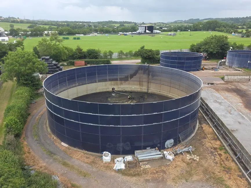
Rectangular (conventional and high-rate lamella) DAF uses full-width plates to raise effective separation area in a compact footprint, is widely deployed in food processing, and reaches hydraulic loadings up to 50 m³/m²·h, but it is sensitive to feed distribution and short-circuits when the solids band swings (Clean Technology Post, 2026). Circular (radial-flow) DAF uses central flocculation and peripheral skimming, handles high solids and variable flows, and is the geometry Clean Technology Post names for slaughterhouse and rendering service (Clean Technology Post, 2026). The default choice on a rendering line is therefore circular, with rectangular high-rate DAF reserved for pre-conditioned feeds and tight footprints. Skimmer selection follows geometry: continuous belt or beach-style skimmers on rectangular units minimise floc breakage, while peripheral scrapers on circular units handle the thicker sludge blanket typical of rendering duty (Clean Technology Post, 2026). On either geometry, dense grit and bone fines settle to the floor regardless of the bubble action, so a bottom scraper must be specified (Clean Technology Post, 2026).
| Criterion | Rectangular (lamella) DAF | Circular (radial-flow) DAF |
|---|---|---|
| Best feed character | Pre-conditioned, narrow solids band | High and variable solids, batch shocks |
| Hydraulic loading ceiling | Up to 50 m³/m²·h with plate packs | 5–30 m³/m²·h typical |
| Skimmer style | Continuous belt / beach skimmer | Peripheral scraper |
| Sensitivity to inlet distribution | High — short-circuits under swing | Lower — radial flow dampens swings |
| Rendering/slaughterhouse precedent | Food processing, not rendering | Named for slaughterhouse and rendering service |
| Bottom scraper | Required for grit and bone fines | Required for grit and bone fines |
Upstream and downstream unit operations the DAF must be integrated with
The DAF is a node in a train, and Kemco Systems is explicit that a typical system includes coarse filtration, physical-chemical treatment, and sludge dewatering prior to discharge or reuse. Upstream of the DAF, a hydrocyclone or shaker screen removes lint, scale, sand and other large objects—the hydrocyclone is a centrifugal separator built for high-density solids such as sand and gravel, and the shaker screen is a multi-stage filtration that can handle varying flow rates and separate both fine and coarse particles (Kemco Systems). pH control sits ahead of chemical conditioning and flotation, with automatic acid or caustic addition driven by an in-tank pH sensor and metering pumps; without it, coagulant performance collapses and the discharge risks sewer violations (Kemco Systems).
Downstream, DAF skimmings leave the tank at 2–6% dry solids, which is thick for a flotation sludge and is ready for mechanical dewatering rather than a settling tank (Clean Technology Post, 2026). A plate-and-frame filter press for DAF sludge dewatering is the standard finish—Kemco Systems notes that filter presses process sludge from DAF and similar operations, significantly reducing waste volume and lowering hauling and disposal cost. Chemical conditioning is delivered through an automatic coagulant and flocculant dosing skid matched to the jar-tested polymer programme. The DAF unit itself is typically a packaged circular or rectangular DAF skid covering 4–300 m³/h with the saturator, recycle pump and skimmer pre-assembled. For plants pursuing water reuse, Clean Technology Post notes that DAF plus biological polishing is the standard rendering train and that hybrid DAF-MBR schemes are emerging as a route to closed-loop operation.
Worked sizing logic for a rendering DAF

The procedure below maps the parameter table to a real project without inventing numbers beyond the research ranges. Step 1: Characterise the waste stream by pulling FOG, TSS, BOD/COD, temperature and pH from composite and grab samples, and derive a peak factor from the cooker dump schedule before any tank geometry is chosen. Step 2: Set the design A/S ratio inside the 0.005–0.06 mL air per mg solids window from Clean Technology Post; for FOG- and protein-rich rendering streams, jar-test at the upper end of that band to confirm floatability. Step 3: Pick hydraulic loading inside the 5–30 m³/m²·h range; deeper tanks of 2–3 m give better separation distance at higher civil cost, so iterate footprint against the civil budget (Clean Technology Post, 2026).
Step 4: Size the recycle pump for 20–40% of forward flow at 4–6 bar saturator pressure, then verify the saturator achieves 80–95% air saturation at design temperature (Clean Technology Post, 2026). Step 5: Always validate on-site with jar testing or a pilot study—both Kemco Systems and Clean Technology Post treat pilot work as indispensable for a rendering design because FOG emulsification and protein surface chemistry vary site to site. The engineer can compare their finalised envelope against the best DAF unit for industrial wastewater 2026 decision framework before issuing a bid list.
Common design mistakes on rendering DAF projects
Designing only for average flow rather than batch cooker peaks is the most common error; rendering duty is shock-loaded and the saturator, skimmer and sludge line must be sized for peak hour, not daily mean. Skipping pH control and chemical jar testing means emulsified FOG and protein will not float, and the DAF will look like it has failed when the chemistry is the problem (Kemco Systems; Clean Technology Post, 2026). Using a rectangular lamella DAF on a stream with bone fines and grit causes the inlet distribution to fail and the lamella pack to pack with grit, so insist on a bottom scraper or move to circular geometry. Undersizing the dewatering stage is the silent bottleneck: DAF sludge at 2–6% solids still needs a plate-and-frame filter press for DAF sludge dewatering to be disposable, and the press area—not the DAF—often governs the hydraulic envelope (Kemco Systems).
Frequently asked questions
What air-to-solids ratio should we target for a high-FOG rendering stream?
Clean Technology Post (2026) sets the A/S range at 0.005–0.06 mL of air per mg of solids, and notes that insufficient air yields poor removal while excess air wastes energy and disrupts the sludge blanket. For a FOG- and protein-rich rendering stream, the design point sits at the upper end of that band, but the actual dose must be confirmed by jar testing on the rendering stream; polymer choice and emulsion stability move the optimum enough that an off-the-shelf number is not defensible.
How do we choose between circular and rectangular DAF for a rendering plant?
Clean Technology Post (2026) names circular, radial-flow DAF as the geometry used in slaughterhouse and rendering plants because it handles high and variable solids and shock flows; rectangular high-rate DAF with lamella plates is reserved for pre-conditioned feeds and tight footprints. The decision pivots on whether the feed has been stabilised to a narrow solids band—if it has, rectangular DAF reaches up to 50 m³/m²·h; if it has not, circular DAF is the safer choice, with a bottom scraper specified either way for grit and bone fines.
What is the realistic CAPEX range for a rendering DAF and filter press, and what drives it?
The supplied research does not quote a CAPEX figure for a