

The Six Most Common Constructed Wetland Problems at a Glance
Constructed wetlands (CWs) are engineered systems that combine vegetation, substrate, and microbial assemblages to treat wastewater under controlled hydrology, as defined by Vymazal (Water, 2010, doi:10.3390/w2030530). A 2024 review in ScienceDirect (S2214714423010899) identifies four urgent problems: cold-climate risk, plant vulnerability, matrix clogging, and greenhouse-gas (GHG) emissions. Field reports from 2024–2026 add a fifth: poor ammonia removal in horizontal-flow (HF) CWs, and a sixth: industrial shock loading on metal-laden influents. Use the table below to self-diagnose in under a minute.
| Symptom in the field | Likely cause | Severity | First-action fix |
|---|---|---|---|
| Ponded surface, slow drawdown | Matrix clogging; TSS load >20 g/m²·d (U.S. EPA via Vymazal, 2010) | High | Add sediment forebay; install rotary mechanical bar screen upstream |
| Ammonia >15 mg/L in winter | Bed temperature <10 °C for >2 weeks; HF oxygen limitation (Vymazal, 2010, §2.2) | High | Add tidal vertical-flow (VF) stage; insulate bed surface |
| Plant die-off after one season | Species mismatch with influent salinity or metal load (Silesian/EMSE thesis, 2013) | Medium | Switch to Phalaris/Iris/Typha mix; harvest annually |
| Methane/nitrous-oxide flux spikes | Anaerobic pockets in saturated HF beds (ScienceDirect, 2024) | Medium | Convert to VF or tidal fill-and-drain operation |
| Footprint exceeds site envelope | Single HF bed at 5 m² PE⁻¹ (Vymazal, 2010, §2.2) | Medium | Stage VF→HF hybrid at 1–3 m² PE⁻¹ on the VF side |
| Toxic event after metal spike | Untreated electroplating or mining influent (S1, 2013) | High | Add chemical precipitation + lamella clarifier before the bed |
Matrix Clogging: Causes, Warning Signs, and Engineering Fixes
Clogging is the leading cause of CW underperformance and traces to three mechanisms: suspended-solids accumulation, biofilm overgrowth, and chemical precipitation of iron, calcium, or phosphorus compounds (Vymazal, 2010, §2.2; ScienceDirect, 2024). The safe operating envelope for a horizontal subsurface flow constructed wetland is 20 g TSS/m²·d and 6 g BOD₅/m²·d, the U.S. EPA inflows that hold effluent BOD₅ and TSS at 30 mg/L (per Vymazal, 2010, §2.2). VF beds tolerate higher short-term pulses because unsaturated flow draws oxygen in between dosings, but they still need rest cycles of several hours per dose.
Design fixes that prevent clogging:
- Media selection: washed gravel 10–20 mm grain size for HF beds; finer sand 0–4 mm in the top layer of VF beds for TSS polishing (Vymazal, 2010, §2.2–2.3).
- Hydraulic regime: intermittent dosing on VF beds, typically 4–6 pulses/day with a 4–6 hour rest, keeps the bed aerobic and limits biofilm thickness.
- Upstream protection: a sediment forebay sized at 5–10% of bed area captures coarse grit; a DAF pre-treatment system drops influent TSS below the 20 g/m²·d threshold for difficult streams.
- Solids removal: a rotary mechanical bar screen with 3–6 mm openings protects the bed from rags and plastic that cause short-circuiting.
- Emerging filler: the 2024 e-PCW study (Hou et al., Bioresource Technology, Vol. 407, Article 131115) added pyrite iron-carbon micro-electrolysis filler around the cathode and reported simultaneous anti-clogging performance and residual phosphorus removal in eutrophic water.
Cold-Climate Performance Loss and How to Design Around It
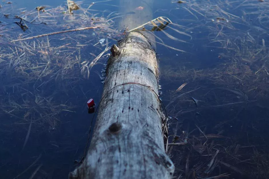
HF CWs lose nitrification in winter because oxygen diffusion through waterlogged substrate is too slow to support nitrifying bacteria, dropping ammonia removal to under 30% when bed temperature falls below 10 °C for more than two weeks (Vymazal, 2010, §2.2; Ji et al. cited in ScienceDirect, 2024). Fan et al. and Ji et al. (both cited in the 2024 review) conclude that VF beds with intermittent loading retain 60–80% of summer nitrification rates in cold regions because each dose draws fresh air into the bed.
Engineering tactics that hold nitrification through winter:
- Switch to tidal fill-and-drain VF: wastewater is pulsed upward until the surface is flooded, held, then drained downward, drawing air into the substrate voids and restoring aerobic conditions between cycles (Vymazal, 2010, §2.3).
- Hybrid VF→HF staging: a smaller VF stage (1–3 m² PE⁻¹) handles ammonia oxidation and a downstream HF stage handles denitrification using carbon from plant litter; this combination outperforms single-type CWs for total nitrogen in cold climates (Vymazal, 2010, §2.4).
- Insulation tactics: leave reed litter in place over winter, increase water depth in FWS cells to 40–60 cm, and cut hydraulic loading by 30–50% from November to March to extend residence time.
- Disinfection integration: a polishing step using ozone water treatment in a side-stream can compensate for partial nitrification failure when reuse-quality effluent is required.
Plant Die-Off, Species Mismatch, and Why Vegetation Is a Process Variable
Wetland plants are process equipment, not ornament: they provide substrate for attached bacteria, radial oxygen loss to the rhizosphere, nutrient uptake, and winter insulation of the bed surface (Vymazal, 2010, §2.2). A monoculture of Phragmites in an industrial CW receiving metal or saline influent typically collapses within 1–2 seasons because the rhizosphere cannot sustain microbial abundance under metal stress; the Silesian/EMSE thesis (2013) on electroplating wastewater polishing in constructed wetland systems explicitly identifies plant–substrate matching as a prerequisite for metal and cyanide removal.
Operational fixes that keep the rhizosphere alive:
- Species mix for industrial loads: Phalaris arundinacea, Iris pseudacorus, Typha, and Schoenoplectus tolerate metals and salinity better than pure Phragmites (Vymazal, 2010, §2.2; S1, 2013).
- Microbial coupling: rhizosphere isolates dominated by Pseudomonadota (Gammaproteobacteria) are positively associated with BOD₅ removal in subsurface-flow CWs, per a 2026 study in Microorganisms (PMC13029343). Plant health is therefore a direct lever on treatment performance.
- Annual harvest: cut above-ground biomass in late autumn to remove stored nitrogen, phosphorus, and metals before litterfall recycles them back to the water column.
- Pre-treatment rule: for electroplating or mining influent, condition the stream to pH 6.5–7.5, oxidize free cyanide to cyanate, and precipitate heavy metals before the bed, otherwise the rhizosphere collapses within weeks.
Greenhouse Gas Emissions: The Hidden Compliance Risk
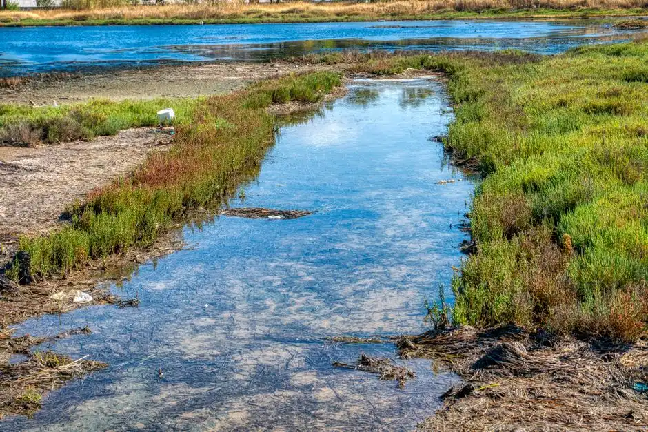
GHG release is one of the four urgent CW problems identified in the 2024 ScienceDirect review, and it is the reason nature-based systems can still carry a non-trivial carbon footprint if poorly designed. Methane forms in the anaerobic pockets of permanently waterlogged HF beds; nitrous oxide escapes when nitrification and denitrification are spatially decoupled and incomplete. Even so, the same review notes that CWs are 2–5× less environmentally impactful than activated sludge on a full life-cycle basis when comparing fossil depletion, ozone depletion, and climate-change categories (ScienceDirect, 2024).
Mitigation tactics that cut CH₄ and N₂O without losing effluent quality:
- Aerate the substrate: convert saturated HF beds to VF or tidal fill-and-drain operation; each drain cycle pulls air into the bed and collapses the CH₄-producing anaerobic volume.
- Complete denitrification: recirculate nitrified effluent (typically 30–50% recycle) to the inlet of an HF stage; this raises the carbon-to-nitrate ratio and closes the N₂O window.
- Bio-electrochemical chamber: the 2024 ScienceDirect review reports that integrating a bio-electrochemical chamber into a CW controls GHG emissions by shifting electron flow away from methanogens.
Land Footprint: Can CWs Still Compete in 2026?
Land is the recurring pinch point when a CW is proposed for a constrained industrial or municipal site. HF CWs are sized at approximately 5 m² PE⁻¹ under the long-standing rule of thumb (Vymazal, 2010, §2.2). VF CWs shrink the footprint to 1–3 m² PE⁻¹ because unsaturated flow oxygenates the bed and accelerates BOD₅ and ammonia removal (Vymazal, 2010, §2.3). A hybrid VF→HF train puts the aerobic load on the smaller VF stage and lets the downstream HF stage finish denitrification, halving the total area relative to a single HF design.
| CW type | Typical sizing (m² PE⁻¹) | Aerobic fraction | Best-fit use in 2026 |
|---|---|---|---|
| Free water surface (FWS) | 5–10 | Low (water column only) | Stormwater, polishing, low-load rural sites |
| Horizontal subsurface flow (HF) | ~5 | Low (root zone only) | Denitrification, BOD₅/TSS polishing |
| Vertical subsurface flow (VF) | 1–3 | High (unsaturated pulse) | Nitrification, small-footprint municipal works |
| Hybrid VF→HF | 3–5 total | High on VF, low on HF | Cold-climate total nitrogen, urban retrofits |
| Packaged MBR (alternative) | <0.1 m² PE⁻¹ equivalent | Fully aerobic | Land-constrained industrial or reuse sites — see MBR packaged wastewater treatment system |
For industrial sites where land is the limiting factor and reuse-quality effluent is required, a packaged MBR delivering <1 µm filtration at 10–2,000 m³/day capacity is often the more reliable answer; route the decision through the framework in the next section before committing to a CW retrofit.
Industrial and Metal-Laden Influent: Special Cases and Pre-Treatment Needs
The Silesian/EMSE thesis (2013) is, to its authors' knowledge, the first study on metal and cyanide removal from electroplating wastewater in subsurface-flow CWs, and it confirms that polishing is technically feasible provided the bed is matched to the influent chemistry. The rule of thumb for any metal- or cyanide-laden stream: pre-condition to pH 6.5–7.5, oxidize free cyanide to cyanate with alkaline chlorination, precipitate heavy metals as hydroxides, and settle or float the sludge before the wetland. Without that train, the rhizosphere collapses within weeks and the bed becomes a metal sink rather than a treatment step.
A defensible 2026 treatment train for electroplating or mining influent:
- Source control: chromium reduction (Cr⁶⁺→Cr³⁺) with ferrous sulfate at pH <3, then neutralization to pH 8–9 for hydroxide precipitation.
- Primary clarification: a lamella clarifier settles metal hydroxides at 2–4 m/h overflow rate; for cyanide-laden streams, route through the cyanide wastewater treatment system guide first.
- Secondary polishing: an MBR drops residual metals and BOD₅ below 5 mg/L before the CW; this is where the wetland earns its keep as a low-cost ammonia and trace-metal polisher rather than a primary clarifier.
- Bed loading guardrails: keep influent TSS <30 mg/L, total metals <10 mg/L, and free cyanide below detection at the bed inlet to protect plants and microbes.
2026 Decision Framework: Stay with a CW, Retrofit, or Bypass
The UK Constructed Wetland Association (CWA) database documents more than 1,000 beds; the CWA itself was formed in 1999 because poor builds and unscrupulous constructors were a recurring cause of failure (Cooper, Springer 2008, doi:10.1007/978-1-4020-8235-1_13). The decision framework below assumes the CW is correctly designed and constructed; if it is not, the first action is to engage a CWA-credentialed designer rather than retrofit the hydrology.
| Observed problem | Quick fix | Design upgrade | Bypass trigger (route to packaged system) |
|---|---|---|---|
| Matrix clogging | Sediment forebay, plant harvest | Switch to VF or tidal; add iron-carbon micro-electrolysis filler (e-PCW) | If TSS >100 mg/L persists, add a DAF pre-treatment system ahead of the bed |
| Cold-climate ammonia failure | Insulate, reduce winter HLR | Add tidal VF stage; hybrid VF→HF | If <10 °C persists >3 months and reuse is required, polish with MBR |
| Plant die-off | Switch species mix | Match rhizosphere to influent chemistry; install recirculation | If influent is acutely toxic, route through chemical precipitation first |
| GHG spikes | Add recirculation | Tidal VF operation; bio-electrochemical chamber | If carbon-footprint caps apply, consider MBR with biogas capture |
| Footprint too large | Stage hybrid | Compact VF at 1–3 m² PE⁻¹ | If site <2 m² PE⁻¹, an MBR packaged wastewater treatment system is the realistic answer |
| Industrial shock load | Equalization tank | Precipitation + lamella + MBR + CW polish | If free cyanide or total metals >50 mg/L at the source, no CW should receive the raw stream |
Pre-treatment equipment (DAF, bar screen, MBR) and post-treatment equipment such as a chlorine dioxide generator for disinfection polishing are the usual companions that keep a constructed wetland operating inside its design envelope.
Frequently Asked Questions
What is the most common cause of constructed wetland failure?
Matrix clogging from suspended solids is the leading failure mode, triggered when influent TSS exceeds 20 g/m²·d on horizontal subsurface flow beds (U.S. EPA load cited in Vymazal, Water, 2010, §2.2). A sediment forebay, a rotary bar screen, or a DAF pre-treatment system upstream is the standard mitigation.
How much land does a constructed wetland need per person in 2026?
HF CWs are sized at approximately 5 m² PE⁻¹; VF CWs need 1–3 m² PE⁻¹; and hybrid VF→HF systems land at 3–5 m² PE⁻¹ total (Vymazal, 2010, §2.2–2.4). When site area is below 2 m² PE⁻¹, a packaged MBR is the practical alternative.
Can constructed wetlands treat electroplating wastewater?
Yes, but only as a polishing step after pH adjustment, cyanide oxidation, and metal precipitation. The Silesian/EMSE thesis (2013) is the first known study on metal and cyanide removal in subsurface-flow CWs and confirms the need for upstream chemical precipitation and a lamella clarifier before the bed.
Why do constructed wetlands lose ammonia removal in winter?
HF beds stay waterlogged, and oxygen diffusion is too slow to support nitrifying bacteria below 10 °C, dropping ammonia removal under 30% (Vymazal, 2010, §2.2; Ji et al. cited in ScienceDirect, 2024). Tidal vertical-flow beds and hybrid VF→HF trains keep nitrification alive by drawing air into the substrate between dose cycles.
Do constructed wetlands emit greenhouse gases?
Yes. Methane forms in anaerobic pockets of saturated HF beds and N₂O escapes from incomplete denitrification, which is why GHG control is one of the four urgent CW problems in the 2024 ScienceDirect review. Even so, the same review reports CWs are 2–5× less environmentally impactful than activated sludge over a full life cycle.