The 7 Most Common MVR Evaporator Problems (And What They Cost You)
Mechanical vapor recompression (MVR) evaporator common problems and solutions cluster around seven failure modes: heat-exchanger scaling, compressor vibration, boiling-point-elevation (BPE) underdesign, foaming and carryover, condensate contamination, mechanical seal and gasket leakage, and clean-in-place (CIP) cycle underperformance. An MVR evaporator uses a blower or centrifugal compressor to raise vapor saturation temperature and reuse latent heat; a typical double-stage MVR unit consumes around 0.06 kWh per kilogram of water evaporated (Klaren, S5), and standard ENCON forced-circulation configurations handle 500–1,350 gph (ENCON, S2) — a useful sanity check against current plant load.
The seven problems and their typical production cost:
| # | Failure mode | Quantified impact | First action |
|---|---|---|---|
| 1 | Heat-exchanger scaling | 20–50% loss of overall heat-transfer coefficient (U-value); 50% capacity loss in 250–300 hours on a 4-effect dye-stuff evaporator (Klaren, S5) | Check ΔP and CIP recovery % |
| 2 | Compressor vibration | Trip events within days of dirty-impeller operation; root blowers rarely vibrate (Klaren, S5) | Trend vibration; set 1.5x baseline action limit |
| 3 | BPE-driven capacity loss | HTA undersized by tens of percent if BPE is miscalculated (Klaren, S5) | Recalculate ΔT after BPE |
| 4 | Foaming and carryover | Distillate TDS above 10 mg/L target (YASA, S4) | Inspect demister, dose antifoam |
| 5 | Condensate contamination | Persistent COD/BOD bleed-through with no foam signature | Pressure-test heat-exchanger bundle |
| 6 | Seal and gasket leakage | Compressor amp creep; falling separator vacuum | Log amp trend; replace seals on schedule |
| 7 | CIP underperformance | Post-CIP evaporation rate trending down cycle-on-cycle | Restage acid/caustic/oxidizer sequence |
Quantify the cost of each problem before you spend on a fix. A 30% capacity loss on a 1,000 gph unit is roughly 300 gph of haulage cost at $0.01–$0.02 per gallon of operating cost (ENCON, S2) — about $26,000–$52,000 per year in disposal value alone, before the operator cost of running an under-sized unit.
Heat-Exchanger Scaling: Symptoms, Root Cause, and Fix
Fouling strips 20–50% of the heat-transfer coefficient from a working MVR, and Klaren documents a 50% capacity drop in 250–300 hours on a dye-stuff effluent's first effect (Klaren, S5). The symptom ladder runs in a predictable order: falling evaporation rate at constant compressor load, rising compressor ΔT, increasing ΔP across the heat exchanger, and lengthening CIP cycles for the same recovered U-value. By the time the operator sees distillate quality drift, the tube wall is already scaled.
Root cause is hard, crystalline, biological, or particulate deposits forming on the hottest tube wall — most severe in the first effect, where vapor saturation temperature peaks. Dye-stuff effluent is a textbook example because salts and organics co-precipitate into a thick, hard scale (Klaren, S5).
Three fix paths, in escalating cost:
- Chemistry first. Optimize antiscalant dose and pH window; verify with an on-stream heat-transfer trend or a coupon in the recirculation loop. This is the cheapest intervention and the one most often skipped.
- Mechanical cleaning. Open cleaning, brush-and-ball, or high-pressure water jet. Effective but labor-intensive and a multi-day outage on a shell-and-tube bundle.
- Retrofit. Replace the first effect with a self-cleaning fluidized-bed heat exchanger using 1.6–4 mm stainless or ceramic particles. Capacity held constant post-retrofit on the dye-stuff plant referenced above (Klaren, S5).
Decision rule: if capacity recovery after CIP falls below 90% of nameplate in two consecutive cycles, the heat exchanger is the bottleneck — not the chemistry. At that point, accept the CIP cost, plan a retrofit, or move upstream salt rejection with a HydropureWater Industrial Reverse Osmosis system to lower the scaling load on the evaporator.
Compressor Vibration and Rotor Fouling
Rising vibration on a turbofan or centrifugal compressor is the earliest reliable warning of rotor fouling — usually well before any temperature alarm fires. Vapor-side deposits build on the high-tip-speed impeller, unbalance the rotor, and the bearing housing sees it first. Root blowers (rotary lobe / positive-displacement) are more robust and rarely vibrate, because their two-piston geometry tolerates fouling without unbalance (Klaren, S5).
The Gotsu Mill case confirms this failure mode is real and resolvable: after MVR startup in 2019, scale-induced heater blockage and compressor vibration both surfaced, and open washing of the compressor resolved the vibration to stable operation (Japan TAPPJ, S1). The take-away is sequencing — do not run a turbofan with a dirty impeller to "save the schedule." Bearing damage follows within days, and a turbofan rebuild is a multi-week outage.
Action set for the on-call engineer:
- Trend vibration weekly; set a 1.5x-baseline action limit and a trip level at roughly 2x baseline.
- Schedule an open wash the moment the trend bends, not when the alarm fires.
- Specify compressor type to match the duty: rotary lobe / roots blower for small, dirty, or intermittent streams; centrifugal for large, clean, continuous flows (ENCON, S2).
Boiling-Point Elevation: The Sizing Error That Looks Like a Scaling Problem
Boiling-point elevation is the silent capacity killer that no amount of CIP will fix. Dissolved salts raise the boiling point of the liquor above pure-water saturation at the same pressure, and that delta eats directly into the temperature driving force (ΔT) across the heat exchanger. Underpredict BPE and the chosen heat-transfer area (HTA) comes in too small — by tens of percent in some cases (Klaren, S5).
Klaren's worked example is worth memorizing: 100°C atmospheric vapor with an 8°C BPE means the liquid boils at 108°C. A two-stage compressor with a 16°C temperature rise condenses vapor at 116°C, leaving roughly 8°C of usable ΔT. A single-stage compressor with only 8°C of rise leaves zero driving force — the unit cannot evaporate (Klaren, S5).
| Compressor configuration | Compressor ΔT (°C) | Liquid boiling point (°C) | Usable ΔT after 8°C BPE |
|---|---|---|---|
| Single stage | 8 | 108 | ~0°C — no evaporation |
| Two stage | 16 | 108 | ~8°C — borderline |
| Two stage + 5°C HTA margin | 16 | 108 | ~8°C, with design margin |
Symptom signature: capacity is short even on a freshly cleaned exchanger, and the gap widens as the liquor concentrates. The fix is engineering, not operations — specify two-stage compression, add HTA margin, or strip salts upstream before they reach the evaporator body with a HydropureWater Industrial Reverse Osmosis system so BPE stays in a controllable band.
Foaming, Carryover, and Condensate Contamination
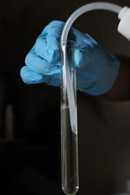
Distillate conductivity or TDS climbing above the 10 mg/L reuse target (YASA, S4) is the trigger to investigate. Two failure paths produce the same headline number, and the operator has to tell them apart before treating the wrong one.
Foam carryover comes from organics or surfactants in the feed — the giveaway is visible foam in the separator and a wet demister pad. Fix with anti-foam dosing (silicone or alcohol-based, selected against the feed chemistry) and a demister inspection.
Leaking heat-exchanger tube produces persistent distillate contamination with no foam signature and no benefit from anti-foam. The fix is mechanical: pressure-test the bundle, isolate the leaking channel, and plug or replace the affected tubes.
Process tip: ENCON's forced-circulation flash design suppresses boiling inside the heat exchanger by holding the loop above saturation pressure until the orifice plate, which materially reduces carryover versus a natural-circulation design (ENCON, S2). If carryover is a chronic problem, the loop hydraulics — not just the chemistry — deserve a look.
Mechanical Seals, Gaskets, and Vacuum Loss
Seal and gasket leaks do not trip process alarms; they quietly bleed capacity and energy. The symptom set is gradual: rising compression work (compressor amp creep) for the same evaporation rate, falling vacuum at the separator, and salt deposits crystallizing on flange faces around the circulating loop. Log amp trend weekly and the leak often shows up as a slope change long before a gauge moves.
Fix path: scheduled seal replacement on hours-run, torque-check flanges after thermal cycling, and treat any visible salt creep at a flange as a load-bearing data point — it means vapor is escaping. ENCON specifies ASME Section VIII pressure vessels with rupture disks as baseline (ENCON, S2); use that scope to benchmark whether your vendor's mechanical-safety design matches.
CIP Cycle Underperformance: When 'Clean-in-Place' Stops Cleaning
Post-CIP evaporation rate trending down over successive cycles is the signature: the exchanger is being "cleaned" but the U-value recovery is shrinking. Three common root causes, in order of frequency:
- Wrong chemistry sequence. A single acid wash will not remove biofilm; a single caustic wash will not remove sulfate scale.
- Temperature too low. Scale solubility drops sharply below 60–70°C; a tepid CIP leaves deposit behind.
- Flow maldistribution. Tubes at the bundle periphery see full flow while center tubes see almost none — verify with bundle-side ΔP and flow.
Stage the chemistry: alkaline soak for organic or biological film, acid wash for carbonate or sulfate scale, oxidizer (typically hydrogen peroxide or sodium hypochlorite, dose-controlled) for biological fouling. Verify recovery with an on-stream heat-transfer trend, not visual inspection of the return line. ENCON's automated CIP loop running on Allen-Bradley controls with continuous temperature, pressure, and level monitoring (ENCON, S2) is a fair benchmark for what "good" automation looks like — if your CIP is operator-driven and on timers, that gap is part of the problem.
Retrofit vs. Accept: The Field Decision Rule
After the next CIP cycle, apply this binary rule:
Retrofit the first effect with a self-cleaning fluidized-bed heat exchanger when (a) capacity recovery after CIP is below 90% of nameplate for two cycles in a row, and (b) the deposit is hard, crystalline, or biological rather than soft sludge. The Gotsu Mill MVR retrofit reached 111% of baseline pulp output and cut energy cost by 13% versus a multi-effect vacuum evaporator (Japan TAPPJ, S1) — proof that the decision pays back on hard-to-clean streams.
Accept the CIP cost when the stream is low-TDS, the duty is intermittent, and the heat exchanger is plate-and-frame (easier to open) rather than shell-and-tube. In that case, optimizing chemistry and CIP sequencing returns more value than capital.
Energy framing for the meeting: MVR at 0.06 kWh/kg uses about 41% less primary energy than a 4-effect MEE with TVR at 0.28 kg steam/kg (Klaren, S5). That number is the floor — the failure modes above determine whether the plant actually lives at the floor or pays a 20–50% U-value penalty on top of it.
Frequently Asked Questions
What is the most common cause of MVR evaporator capacity loss?
Heat-exchanger scaling on the first effect, which strips 20–50% of the heat-transfer coefficient and can cut evaporation capacity by 50% within 250–300 hours on dye-stuff effluent (Klaren, S5). Diagnose by trending compressor ΔT and bundle ΔP; verify with CIP recovery percentage.
How do I tell compressor vibration from normal bearing wear?
Trend vibration weekly and set a 1.5x-baseline action limit. A steady upward trend on a turbofan or centrifugal compressor indicates rotor fouling on high-tip-speed impellers; root blowers tolerate fouling and rarely vibrate (Klaren, S5). Schedule an open wash before the trip level — running a dirty turbofan to "save the schedule" typically damages bearings within days.
When should I retrofit a self-cleaning fluidized-bed heat exchanger instead of running more CIP?
Retrofit the first effect when CIP recovery falls below 90% of nameplate for two consecutive cycles and the deposit is hard, crystalline, or biological. The Gotsu Mill MVR retrofit delivered 111% of baseline pulp output and 13% energy savings versus a multi-effect vacuum evaporator (Japan TAPPJ, S1) — a useful proof point for the capital request.
What upstream equipment lowers scaling and BPE on an MVR evaporator?
Reject salts upstream with a HydropureWater Industrial Reverse Osmosis system, and handle the resulting concentrate solids with a HydropureWater plate and frame filter press. Lower inlet TDS means lower BPE, softer scale, and longer CIP intervals. For broader treatment-plant context, see this field guide on anaerobic digester common problems and solutions and this comparison of how to compare reliable industrial wastewater treatment solutions.