What Is an EGSB Reactor and Why It Exists
An expanded granular sludge blanket (EGSB) reactor is a high-rate anaerobic digester that treats wastewater by passing influent upward through a bed of dense methanogenic granules at a superficial velocity of 4–10 m/h, made possible by a tall height-to-diameter geometry and effluent recirculation (per ScienceDirect S3, 2012). The EGSB was introduced by Gatze Lettinga and colleagues in the 1990s specifically to overcome the limitations of the upflow anaerobic sludge blanket (UASB) reactor when handling low-strength soluble wastewaters and streams containing toxic or inhibitory compounds (per ScienceDirect S3).
The design rests on three engineering pillars: (i) exclusive use of well-formed granular sludge as the active biomass, (ii) operation under a controlled slight bed expansion of roughly 10–30%, and (iii) the expectation that granules will remain physically stable while gradually augmenting their attached biofilms as the system matures (per ScienceDirect S3). Compared with the settled sludge bed in a conventional UASB, the partially fluidized condition in an EGSB improves substrate diffusion from bulk liquid to the liquid–granule interface, which is the rate-limiting step for methanogenic conversion in cold or dilute streams.
By 2008, more than 200 full-scale EGSB reactors had been built worldwide, with individual reactor volumes ranging from 30 to 5,000 m³ (per ScienceDirect S3, Table 11). EGSB is now the second most widely deployed high-rate anaerobic digester after the conventional UASB, and it is the technology of choice in many breweries, food plants, and chemical operations where the influent is largely soluble and often below 1,000 mg/L COD.
The Working Principle, Step by Step
The EGSB operating sequence can be broken into five physical stages that an engineer can sketch on a P&ID. Understanding the flow path is the difference between specifying a reactor correctly and chasing chronic performance problems after startup.
- Influent distribution. Screened and equalized wastewater enters through a bottom header system with multiple nozzles arranged to deliver uniform upflow across the full reactor cross-section. Poor distribution is the single most common cause of channeling and dead zones in tall EGSB vessels.
- Granular sludge blanket expansion. As influent and recirculated effluent rise, they partially fluidize the 1–3 mm methanogenic granules that form the bed. Unlike the settled UASB blanket, the EGSB bed occupies a larger fraction of the reactor volume and remains in gentle suspension, which increases solids–liquid contact.
- Three-stage anaerobic conversion inside the granules. Dissolved substrate diffuses from bulk liquid into the granule biofilm, where hydrolysis and acidogenesis convert complex organics to volatile fatty acids, acetogenesis converts those to acetate, hydrogen, and CO₂, and methanogenesis converts acetate and H₂/CO₂ to methane. Methanogenic archaea sit in the deeper, older layers of the granule, while acidogens populate the outer shell (per ScienceDirect S3).
- Biogas collection and gas–solids separation. Biogas bubbles rise to a top-mounted gas–solids separator (GSS), where the deflector plates knock entrained sludge back into the bed and the gas exits to the dome for storage or use.
- Effluent overflow and recirculation. Treated water passes over a peripheral weir. A large fraction — typically 50–200% of the forward flow — is pumped back to the reactor base to maintain the 4–10 m/h superficial upflow velocity (Vup) needed to keep the bed expanded (per ScienceDirect S3).
That recirculation loop is the single most important hydraulic feature of the EGSB. It dilutes influent toxic compounds such as tannin, phenol, formaldehyde, and lauric acid to concentrations the methanogens can tolerate, and it is the reason an EGSB can treat streams that a conventional UASB cannot (per ScienceDirect S3).
Key Design and Operating Parameters
The numbers below are the working values engineers lift directly into a datasheet. They are drawn from the Lettinga design rules and the ScienceDirect S3 reference (2012) and remain the basis for EGSB specification in 2026.
| Parameter | Typical EGSB Range | Notes |
|---|---|---|
| Superficial upflow velocity (Vup) | 4–10 m/h | Higher than UASB (<1 m/h); maintained by tall geometry and/or recirculation |
| Height-to-diameter ratio (H/D) | >6 (typically 6–20) | Drives upflow velocity without excessive recirculation energy |
| Bed expansion | 10–30% | Partial fluidization; full fluidization (~50%) risks washout |
| Recirculation ratio | 1:1 to 3:1 (effluent:influent) | Adjusted to hit Vup target and dilute toxics |
| Hydraulic retention time (HRT) | 2.5–12 h (often 4–8 h for low-strength) | Drop to 2.6 h in IC systems; EGSB typically holds 5 h for low-COD streams |
| Organic loading rate (OLR) | Up to 35 kg COD/m³/d | UASB typically fails above 5 kg COD/m³/d |
| Lowest treatable influent COD | <150 mg/L | UASB loses biomass below ~1,000 mg/L |
| Operating temperature | Mesophilic 30–37 °C; psychrophilic stable to 4–10 °C | Rate drops with temperature, but operation remains stable |
| Reactor volume range | 30–5,000 m³ | Based on 200+ full-scale installations by 2008 |
The expanded bed and recirculation are what unlock the upper loading ceiling of 35 kg COD/m³/d and the lower COD floor below 150 mg/L — the two performance extremes that bracket EGSB application (per ScienceDirect S3). The psychrophilic tolerance down to 4–10 °C is unusual among anaerobic systems and is one of the most-cited reasons to select EGSB over a heated UASB in temperate or tropical sites where wastewater arrives cold.
EGSB vs UASB vs IC: How to Choose
EGSB is not a default replacement for UASB or for the more aggressive internal circulation (IC) reactor. The selection hinges on influent strength, particle content, temperature, and the toxic-compound profile. The table below condenses the engineering trade-offs the engineer should walk through before issuing a purchase order.
| Parameter | EGSB | UASB | IC |
|---|---|---|---|
| Superficial upflow velocity | 4–10 m/h | <1 m/h | 8–20× UASB (typically 10–30 m/h in bottom stage) |
| H/D ratio | >6 | ~1 | Very high (two-stage in series) |
| Max OLR | Up to 35 kg COD/m³/d | ~5 kg COD/m³/d | Up to 35 kg COD/m³/d |
| Typical HRT | 5 h (low-COD) to 12 h (high-COD) | 12–48 h | 2.6 h (low-COD) to 8–24 h (high-COD) |
| Influent COD range | <150 to >10,000 mg/L | 3,000–7,000 mg/L | 1,000–23,000 mg/L |
| Min operating temperature | 4–10 °C | >20 °C typical | Mesophilic preferred |
| Solids handling | Soluble wastewaters only | Handles coarse SS and colloids | Soluble wastewaters only |
| Toxic / inhibitor handling | Good — recirculation dilutes tannin, phenol, formaldehyde, lauric acid | Poor — local accumulation in influent zone | Moderate |
| Full-scale deployments | 200+ units, 30–5,000 m³ (per 2008) | Largest installed base globally | 161 units (per 2003); 89 in brewery/soft drink |
| Typical industries | Food, brewery, chemical, slaughterhouse, low-strength effluent | Starch, sugar, beverage, pulp/paper | Brewery (89), pulp/paper (33), food (39), distillery (9) |
The decision rule is straightforward. Choose EGSB when the influent is largely soluble, the COD is low or variable (including <150 mg/L), temperature is sub-20 °C, or the stream contains inhibitory organics that benefit from dilution. Choose UASB when the stream carries coarse suspended solids or colloids and CAPEX must be minimized. Choose IC when high-strength food or brewery wastewater (1,000–23,000 mg/L COD) must be treated at short HRT and high volumetric loading (per ScienceDirect S3).
Real Performance Data from Operating EGSB Systems
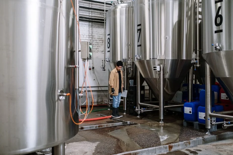
Theoretical parameters are only useful if matched to field results. The numbers below are taken from peer-reviewed operating data and should be used to benchmark a new design.
A microaerobic EGSB system treating domestic wastewater at 15–26 °C achieved 2.2–2.9 m/h Vup at 3.9–4.8 h HRT on an influent of 213–1,145 mg/L COD, 26.5–72.1 mg/L NH₃-N, 31.7–81.7 mg/L TN, and 3.9–16.3 mg/L TP. Effluent concentrations were 26.3 mg/L COD, 9.9 mg/L NH₃-N, 14.0 mg/L TN, and 4.7 mg/L TP, meeting China GB 18918-2002 Class IA–IB reuse standards for COD, NH₃-N, and TN (per IEEE S4, 2011).
EGSB reactors treating slaughterhouse wastewater have demonstrated organic loading rates up to 15 kg COD/m³/d at COD removal efficiencies of 65–80% (per ScienceDirect S3, Table 11). For low-strength soluble wastewaters across the 30–5,000 m³ reactor range, 85% COD removal at 5 h HRT is achievable. The same reference notes that EGSB handles sulphate-containing streams effectively where UASB reactors suffer from sulphide toxicity.
Common Failure Modes and How to Prevent Them
An EGSB runs stable for years when three numbers are kept in range: Vup, OLR, and toxicant loading. When one drifts, performance usually fails in one of four predictable ways.
- Granule washout. Vup above 10 m/h, or sudden hydraulic surges from an unbuffered equalization tank, can drag the 1–3 mm granules over the effluent weir. Prevention: install flow equalization upstream and cap recirculation pump speed to stay inside the 4–10 m/h window.
- Toxic shock. Ammonia, sulphide, or heavy metals can accumulate in the influent zone and shut down methanogenesis. Prevention: characterize influent for known inhibitors and use the recirculation loop to dilute shock loads — the same mechanism that lets EGSB treat tannin, phenol, and formaldehyde (per ScienceDirect S3).
- Channeling and dead zones. Poor distributor design or an H/D ratio below the recommended minimum of 6 lets flow short-circuit one side of the reactor while starving the other. Prevention: design for H/D >6 and verify distributor nozzle count against the cross-section during detail engineering.
- Low methanogenic activity. Cold feed temperatures below 10 °C reduce specific activity even though operation remains stable, and insufficient HRT starves the slower-growing archaea. Prevention: capitalize on the EGSB's 4–10 °C psychrophilic tolerance (per ScienceDirect S3) but accept the rate reduction; size HRT to the design temperature rather than copying a mesophilic datasheet.
Where EGSB Fits in a 2026 Industrial Wastewater Train
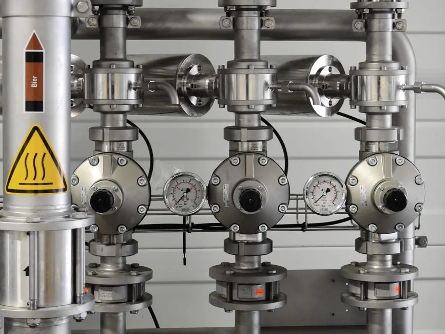
An EGSB is the biological workhorse in the middle of an industrial wastewater train, not a standalone solution. Upstream, raw effluent must be screened and flow-equalized; downstream, the anaerobic effluent still carries residual COD, suspended solids, nutrients, and often phosphorus that must be polished before discharge or reuse.
A typical 2026 industrial train looks like this: rotary mechanical bar screen for coarse solids removal, equalization basin for flow and load buffering, the EGSB reactor for COD reduction and biogas production, then either an MBR membrane bioreactor for reuse-grade effluent or a DAF system for suspended-solids polishing. When the upstream wastewater carries phosphorus that the anaerobic step cannot remove, an automatic chemical dosing system is paired with the EGSB effluent to precipitate phosphate, as in the microaerobic EGSB + chemical coagulation case where Al³⁺ or Fe³⁺ dosing brought TP below 0.5 mg/L (per IEEE S4). For a full SBR-based reuse design with cycle calculations, the SBR design guide for 2026 is a useful reference.
Sludge management is the final step. The wasted granular and flocculent biomass from the EGSB typically goes to a plate and frame filter press for dewatering before disposal or land application. For plants planning modular or containerized treatment skids, the decentralized wastewater treatment forecast to 2030 and the broader industrial wastewater treatment engineering guide provide additional procurement context.
Frequently Asked Questions
What is the main difference between an EGSB and a UASB reactor?
The EGSB operates at a superficial upflow velocity of 4–10 m/h versus <1 m/h in a UASB, achieved by a tall H/D ratio (>6) and effluent recirculation. This expanded bed improves substrate–biomass contact and lets the EGSB treat low-strength wastewaters below 150 mg/L COD and streams containing toxic compounds such as tannin, phenol, and formaldehyde that would accumulate and fail a UASB (per ScienceDirect S3).
What upflow velocity should an EGSB be designed for?
Design Vup should fall in the 4–10 m/h window, with 5–6 m/h being a common operating point for many industrial wastewaters. Vup above 10 m/h risks granule washout, while Vup below 4 m/h lets the bed settle and the reactor behave like a UASB (per ScienceDirect S3).
What is the maximum organic loading rate for an EGSB reactor?
An EGSB can be loaded up to 35 kg COD/m³/d, roughly 7× the practical ceiling of a conventional UASB reactor, which typically fails above 5 kg COD/m³/d. Slaughterhouse installations have run at 15 kg COD/m³/d with 65–80% COD removal, and low-strength soluble streams have reached 85% COD removal at 5 h HRT (per ScienceDirect S3).
Can EGSB reactors operate in cold weather?
Yes. EGSB reactors are stable down to 4–10 °C under psychrophilic conditions, an unusually wide temperature window among high-rate anaerobic digesters. Specific methanogenic activity drops at low temperature, so HRT must be sized to the design winter temperature rather than copied from a mesophilic datasheet (per ScienceDirect S3).
Can an EGSB handle suspended solids?
No — not efficiently. The high upflow velocity that expands the bed prevents effective entrapment and hydrolysis of coarse suspended particles and colloids, so EGSB is restricted to essentially soluble wastewaters. For streams with significant SS or colloidal load, a UASB is the more appropriate choice or a solids-removal step must precede the EGSB (per ScienceDirect S3).