What Sand Filter Design Criteria Actually Control
Design criteria for a sand filter are the coupled set of parameters that, taken together, fix both effluent quality and operating cost: hydraulic loading rate, media effective size (d10) and uniformity coefficient (UC), bed depth, freeboard, underdrain type, and backwash rate/expansion. A specification that fixes any one of these in isolation produces a non-optimal design — push loading rate to 15 m/h without re-checking media, and runtime collapses; coarsen the sand to 0.8 mm without adjusting freeboard, and the bed loses material on every backwash.
The governing trade-off is footprint versus runtime: higher hydraulic loading rates cut filter area and capex but shorten the run between backwashes and tighten the backwash system's design margin. Per S3, secondary effluent entering a tertiary filter typically carries 10–30 mg/L TSS, and a well-operated rapid sand filter will bring that to below 5–10 mg/L — a target that frames the rest of the sizing work.
In the United States, tertiary filtration design is anchored to NPDES permits issued under the Clean Water Act, with state agencies frequently imposing criteria more stringent than the federal baseline (S3). In California, the State Water Resources Control Board's Title 22 Water Recycling Criteria sets the engineering numbers for reuse; in the EU, the Urban Wastewater Treatment Directive (91/271/EEC) and reuse Regulation 2020/741 set the equivalent envelope. The effluent target, not the equipment, drives the design.
Three Operating Regimes: Slow, Rapid Gravity, and Pressure Sand Filters
The operating regime is the first design decision, and it should be made before any sizing number is used. The three regimes differ in loading rate, mechanism, footprint, and operator attention — the comparison below allows a process engineer to select the appropriate system.
| Regime | Loading rate | Removal mechanism | Backwash | Footprint | Typical duty |
|---|---|---|---|---|---|
| Slow sand | 0.1–0.3 m/h | Biological (schmutzdecke) + straining | None; manual scraping | Large (hundreds of m² per ML/d) | Drinking-water pretreatment, small community reuse |
| Rapid gravity | 5–15 m/h | Physical straining; optional coagulant dose | 36–45 m/h water + air scour | Compact (5–15 m² per ML/d) | Municipal tertiary, industrial polishing |
| Pressure | 5–15 m/h | Same as rapid gravity, closed vessel | 36–45 m/h, triggered on ΔP | Compact; vertical/horizontal vessel | Industrial duty, package plants, RO pretreatment |
Slow sand filters run at 0.1–0.3 m/h and rely on the biologically active schmutzdecke at the sand surface for pathogen and turbidity removal; they need no coagulation, no backwash system, and minimal operator attention, but demand a large footprint and periodic manual scraping (S3). Rapid gravity sand filters run at 5–15 m/h, use physical straining with optional coagulant dose, and require an engineered backwash system — they are the default for municipal tertiary and industrial polishing duty. Pressure sand filters enclose the same media in a steel vessel, suiting industrial and package-plant duty where the feed is already under pressure; design criteria for media and loading are otherwise identical to gravity units (S3). A useful rule of thumb: anything that fits on a concrete slab is rapid gravity or pressure; anything that needs a field is slow sand.
Consolidated Design-Criteria Table for All Three Filter Types

The table below consolidates the parameters a process engineer is expected to fix during design. Numbers are typical industry practice, drawn from S3 and standard engineering references; the table is intended for use in a project specification or datasheet, with the caveat that influent character and local code will shift the exact values. Engineers specifying for RO pretreatment should review the multi-media filter for RO pretreatment envelope, which uses the same hydraulic envelope with a coarser-to-fine media stack.
| Parameter | Slow sand | Rapid gravity | Pressure |
|---|---|---|---|
| Hydraulic loading rate | 0.1–0.3 m/h | 5–15 m/h (10 m/h typical) | 5–15 m/h |
| Media effective size (d10) | 0.15–0.35 mm | 0.45–0.65 mm | 0.45–0.65 mm |
| Uniformity coefficient (UC) | 2–5 | 1.3–1.7 | 1.3–1.7 |
| Bed depth | 0.9–1.5 m | 0.6–1.0 m | 0.6–1.0 m |
| Freeboard | Supernatant 0.5–1.0 m above sand | ≥50% of bed depth | ≥50% of bed depth |
| Backwash rate | None | 36–45 m/h | 36–45 m/h |
| Bed expansion at backwash | N/A | 20–30% | 20–30% |
| Air scour (if used) | N/A | 60–80 m/h | 60–80 m/h |
| Operating pressure | Atmospheric | Atmospheric | 4–6 bar |
| Backwash trigger | Manual scrape (months) | Headloss or timer (24–48 h) | ΔP 0.7–1.0 bar or timer |
| Typical effluent TSS | <1–5 mg/L | <5–10 mg/L | <5–10 mg/L |
Underdrain selection follows the same logic. Gravel support layers graded in size beneath the sand prevent sand migration into the underdrain (S3); modern designs replace the gravel with a false-bottom nozzle plate (typically 5–10 mm orifices on a 50–100 mm pitch), which eliminates gravel inventory and gives more uniform backwash distribution. Either is acceptable; the backwash system must be sized against the underdrain chosen.
Media Gradation: Effective Size, Uniformity Coefficient, and Layering
Media choice often determines field performance outcomes. Effective size (d10) is the sieve aperture that passes 10% of the media by mass; for rapid sand filters, d10 sits in the 0.45–0.65 mm range, with a uniformity coefficient (d60/d10) of 1.3–1.7. Higher UC means broader grading — more fines and more coarse grains in the same bed — and earlier breakthrough of turbidity and headloss, because the fines pack into the voids and the coarse grains let particles pass. A common procurement trap is accepting a silica sand at d10 0.55 mm and UC 2.2; the UC is the critical factor, not the d10.
For multimedia filters, layer anthracite (d10 0.8–1.2 mm, density ~1.4 g/cm³) over silica sand (d10 0.45–0.65 mm, density ~2.65 g/cm³) over garnet or ilmenite (d10 0.2–0.3 mm, density >4.0 g/cm³). The coarse-to-fine grading in the flow direction lets the bed hold roughly 2–3× the solids of a single-media bed before terminal headloss, which directly extends the run between backwashes. Freeboard must accommodate the backwash-expanded bed plus at least 50% safety, otherwise media is lost to overflow during washing — and S3 notes that channeling is a leading cause of poor performance and is partly a media-and-freeboard problem.
Specify at least one alternative media source at bid time. Single-source silica or anthracite supply is a common construction-stage delay, particularly for larger projects, and qualifying a backup source at spec time is a standard risk-mitigation step.
Backwash Hydraulics: Rate, Expansion, and Sequence
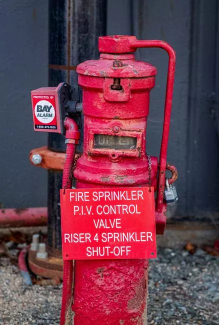
The backwash system is the primary design constraint. Most sand filter problems encountered in the field are not media problems — they are backwash, underdrain, or construction issues (S3), which is why the backwash envelope deserves the same engineering attention as the media itself.
Backwash rate for rapid sand filters sits at 36–45 m/h, sized to fluidize the bed and achieve 20–30% expansion. Below this band, the bed is not cleaned — the grains stay in contact and biofilm accumulates; above it, media is lost to the washwater gullet. Modern sequences combine air scour at 60–80 m/h with a concurrent or follow-on water backwash; air scour alone collapses the bed locally and shears biofilm more effectively than water alone, and is now standard on most municipal installations.
Cell count is part of the backwash design. With one cell offline for washing, the remaining cells operate at an elevated rate. In the worked example in the next section, an 8,000 m³/d plant with four cells sees the three running cells reach approximately 13 m/h during a wash — still within the 5–15 m/h design envelope (S3). A two-cell plant at the same flow would push 16.7 m/h during a wash, exceeding the envelope and risking media loss and short runs. Size the cell count so that the peak-in-wash rate stays inside the design envelope, not just the average rate. At 10 m/h on typical secondary effluent, a rapid sand filter runs 24–48 h between washes; significantly shorter cycles point to media, underdrain, or influent-character problems rather than loading alone.
Worked Sizing Example: 8,000 m³/d Tertiary Polishing Plant
These figures demonstrate how the design criteria integrate into a verifiable sizing. The inputs come from S3, and the structure is reproducible against any influent flow by substituting the new value into the same calculation.
- Inputs: 8,000 m³/d ≈ 333 m³/h; design rate 10 m/h; target effluent <5 mg/L TSS for tertiary polishing.
- Filter area: 333 m³/h ÷ 10 m/h = 33.3 m² total.
- Cell count for backwash margin: With one cell out for washing, three cells must carry 333 m³/h, so each cell runs at 333 ÷ 3 = 111 m³/h, which is 111 ÷ 8.5 = ~13 m/h — within the 15 m/h peak envelope. Four cells of 8.5 m² each is the minimum (S3).
- Media spec: 0.6 m sand bed, d10 0.55 mm, UC 1.5, 0.3 m freeboard (50% of bed depth per the design-criteria table), nozzle-plate underdrain.
- Backwash system: 36–45 m/h water backwash with 60–80 m/h air scour; backwash water demand per cell ≈ 8.5 m² × 40 m/h = 340 m³/h for 8–10 min, or 45–57 m³ per cell per wash.
- Effluent check: Secondary influent TSS 10–30 mg/L → rapid sand filter effluent <5–10 mg/L per S3, satisfying the <5 mg/L tertiary target.
If the same plant feeds a reverse osmosis system downstream, the polishing target shifts from TSS to Silt Density Index (SDI), with a typical target of SDI <5 to protect RO membranes. Multimedia polishing — anthracite over sand over garnet — achieves SDI <5 more reliably than single-media sand in the same footprint, and is the standard upgrade path at this scale. For RO pretreatment sizing, the RO design criteria 2026 reference covers the downstream envelope, and the filter media, valves and underdrain components catalog covers the consumable side of the same design.
Frequently Asked Questions
What hydraulic loading rate should I use for a rapid sand filter on tertiary duty?
Design
Frequently Asked Questions
What is the typical hydraulic loading rate for a rapid sand filter?
The typical hydraulic loading rate for a rapid sand filter ranges from 5 to 12 meters per hour (approximately 2 to 5 gallons per minute per square foot). In high-rate applications designed under 2026 standards, this may be pushed to 15 meters per hour, provided that influent turbidity levels remain consistently low and effective pretreatment, such as coagulation and flocculation, is maintained.
How deep should the sand bed be in a rapid gravity sand filter?
A standard rapid gravity sand filter bed should have a total depth between 600 mm and 900 mm. The sand should have an effective size (d10) ranging from 0.45 mm to 0.55 mm and a uniformity coefficient (UC) of less than 1.5 to ensure optimal head loss development and particle removal efficiency.
What backwash rate is required for a sand filter and why?
The required backwash rate is typically between 35 and 50 meters per hour, which is sufficient to achieve a bed expansion of 20% to 50%. This expansion is critical to fluidize the filter media, allowing the sand grains to rub against one another and release trapped suspended solids into the washwater trough for removal.
How many filter cells are needed for a continuous-duty sand filter installation?
A minimum of four filter cells is generally required for continuous-duty installations to ensure operational redundancy. This configuration allows for one cell to be taken offline for backwashing or maintenance while the remaining three cells maintain the design plant capacity without exceeding the maximum allowable hydraulic loading rate.
What is the difference between a multimedia filter and a single-media sand filter?
A single-media sand filter relies on uniform sand, which often results in surface blinding where solids accumulate at the top, leading to rapid head loss. In contrast, a multimedia filter utilizes layers of varying densities and particle sizes—typically anthracite on top, sand in the middle, and garnet at the bottom—to promote depth filtration, which allows solids to be trapped throughout the entire bed thickness rather than just at the surface.