What MBBR Design Parameters Actually Control
MBBR design parameters are the engineering inputs that govern biofilm carrier area, oxygen demand, and effluent quality: media fill fraction (typically 20–70% of reactor volume), specific surface area (Kaldnes K1 ≈500 m²/m³, K3 ≈600, K5 ≈800), hydraulic retention time (1–6 h aerobic, 4–12 h anoxic), dissolved oxygen (2–4 mg/L aerobic, <0.5 mg/L anoxic), and organic loading rate (5–15 g BOD/m²·d). The K1 pilot study at 20% fill achieved 91% BOD and 93.81% COD removal in 10 days (Kusuma et al., 2019, doi:10.26418/jtllb.v7i1.31882).
Seven parameters drive every MBBR sizing decision: carrier type, fill fraction, specific surface area, hydraulic retention time (HRT), organic loading rate (OLR), dissolved oxygen (DO), and wastewater temperature. The cause-effect chain is straightforward: surface area × fill % = effective biofilm area; effective area ÷ OLR = minimum reactor volume; volume ÷ flow = HRT. If any of the seven moves, the others must re-balance, and that is why a vendor quote specifying one number without the others is rarely defensible.
The Guheshwori pilot in Nepal gives the cleanest published proof of why this stack matters (Kusuma et al., 2019, S5). A 16 L lab reactor with 5 L active working volume, run with and without carriers at otherwise identical conditions, removed 89.68% BOD without media versus 96.84% COD and 99.20% NH4-N with media at 24 h. The hydraulic residence time was the same in both cases, so the additional removal is attributable to biofilm surface area, not retention. The S1 laundry study used a single 20% fill and a single K1 media; useful for benchmarking but insufficient for design, which is why the rest of this article scales those values into industrial ranges drawn from the Springer MBBR chapter (Ødegaard, Rusten and Wessman, 2018, S3, doi:10.1007/978-3-319-58835-3_3).
Biofilm Carrier Specifications: K1, K3, K5 and AnoxKaldnes Compared
Kaldnes K1 is the original 7×9 mm cylindrical HDPE carrier, density ~0.95 g/cm³, specific surface area ≈500 m²/m³, and the carrier used in the S1 laundry study at 20% fill. It remains the workhorse for municipal and light industrial plants because of its low cost per m³ of media and well-documented nitrification behavior in the Springer literature (Hem, Rusten and Ødegaard, 1994, cited in S3).
Kaldnes K3 measures 10×8 mm with a more open protected internal area, raising the specific surface area to ≈600 m²/m³. The extra protected area is what carries the biofilm through shock organic loads without sloughing, which is why K3 is the default for combined BOD/nitrification duty. Kaldnes K5 at 25×4 mm pushes the same metric to ≈800 m²/m³ through larger external geometry and is the carrier of choice for high-load industrial effluents and any reactor that must absorb diurnal spikes. AnoxKaldnes-type carriers are larger, denser media designed for anoxic or anaerobic reactors where mixing comes from mechanical stirrers rather than aeration; these are required for the denitrification half of an A2O-MBBR train and are the carrier family referenced in the Fe/Cu micro-electrolysis + A2O-MBBR leachate reactor (Europe PMC, S2, PPR1134129).
The trade-off is real: a higher m²/m³ media packs more biofilm area per m³ of tank but raises headloss, requires stronger aeration, and costs more per m³ of media. Vendors who quote only the protected-area number without the corresponding mixing-energy and blower cost are hiding part of the bill.
| Carrier | Nominal geometry | Specific surface area (m²/m³) | Typical duty | Mixing source |
|---|---|---|---|---|
| Kaldnes K1 | 7×9 mm cylinder | ≈500 | Municipal, light industrial; S1 laundry pilot | Aeration |
| Kaldnes K3 | 10×8 mm | ≈600 | Combined BOD + nitrification | Aeration |
| Kaldnes K5 | 25×4 mm | ≈800 | High-load industrial, shock-load resilience | Aeration |
| AnoxKaldnes-type | Larger, denser | ≈500–700 | Anoxic/anaerobic zones, A2O-MBBR (S2 leachate) | Mechanical stirrer |
Fill Fraction, Specific Surface Area and Effective Biofilm Area
Fill fraction is the volume of carriers expressed as a percentage of the empty reactor volume. The S1 laundry study ran at 20% fill, which is the low end of the commercial range. Most industrial MBBRs are designed between 30% and 67% fill, with the upper limit set by the point at which fluidization quality degrades and the carriers begin to bridge (Ødegaard, 2006, cited in S3).
The arithmetic that connects the abstract m²/m³ to the actual biofilm area installed in the reactor is the key calculation a process engineer has to defend in a spec:
Effective biofilm area = reactor volume × fill fraction × carrier specific surface area.
For a 100 m³ aerobic reactor at 40% fill with K3 carriers: 100 × 0.40 × 600 = 24,000 m² of protected biofilm area. The S1 study authors flagged that 20% fill was a deliberate low-end choice and explicitly recommended that "further research can be carried out with variations in the volume of fill media" (Kusuma et al., 2019). Industrial designs routinely double or triple that fill, which is the single biggest reason the same carrier can produce dramatically different removal numbers at otherwise identical HRT and temperature.
Ødegaard's European MBBR work (S3) makes a related point: it is the protected internal area of the carrier that actually carries biofilm at scale; carriers chosen for a high nominal m²/m³ but low protected area under-perform once the reactor is full-scale. The fill-fraction × specific-surface-area product is the most predictive single number for an aerobic MBBR.
Hydraulic Retention Time and Organic Loading Rate by Application
HRT and OLR move together: shorter HRT forces a higher OLR on a fixed biofilm area, and OLR above roughly 15 g BOD/m²·d typically pushes effluent BOD above 30 mg/L regardless of carrier choice. The bands below are drawn from the Springer MBBR chapter (S3), the Guheshwori pilot (S5), and the S1 laundry study, and they are the ranges an engineer should sanity-check any vendor process guarantee against.
For industrial BOD removal only, design at 1–3 h HRT and 5–15 g BOD/m²·d. For combined BOD removal and nitrification, expect 4–6 h HRT, 2–5 g BOD/m²·d, and DO 2–4 mg/L; the Guheshwori pilot reached 99.20% NH4-N removal in 24 h with 5 L active volume, demonstrating nitrification is achievable at this residence time (S5). For A2O-MBBR on leachate or high-ammonia streams, 6–12 h total HRT split between anaerobic, anoxic and aerobic zones is typical; the Fe/Cu + A2O-MBBR leachate reactor in S2 is the documented industrial example. Laundry and surfactant streams behave differently: the S1 K1/20% pilot needed 10 days to reach 91% BOD and 93.81% COD, which in continuous-flow design translates to long HRT or a downstream MBR polish.
Nitrogen loading rate (NLR) for aerobic nitrification is typically 0.5–2.0 g NH4-N/m²·d; outside this range expect nitrite breakthrough, per Grunditz & Dalhammar (2001, cited in S3). Temperature derating is unavoidable: below 10 °C the nitrification rate falls sharply, and Luostarinen et al. (2006, cited in S3) showed that intermittently aerated cold-climate MBBRs can maintain partial nitrification at near-zero temperatures, but only with conservative carrier and HRT sizing.
| Application | HRT (h) | OLR (g BOD/m²·d) | NLR (g NH4-N/m²·d) | Fill (%) | Reference |
|---|---|---|---|---|---|
| Industrial BOD removal only | 1–3 | 5–15 | — | 30–50 | S3 (Hem et al. 1994) |
| Combined BOD + nitrification (municipal) | 4–6 | 2–5 | 0.5–2.0 | 40–67 | S3; S5 (Guheshwori) |
| A2O-MBBR (leachate / high-ammonia) | 6–12 total | 2–6 | 1.0–2.0 | 40–60 | S2 (Fe/Cu + A2O-MBBR) |
| Laundry / surfactant (K1, 20%) | 10 d batch | Low (lab) | — | 20 | S1 (Kusuma et al. 2019) |
| Textile / food (industrial) | 3–6 | 4–10 | 0.5–1.5 | 40–60 | S3 (Ødegaard 2006) |
Dissolved Oxygen, Mixing and Temperature Setpoints
The operating-side parameters decide whether a designed MBBR actually meets its removal numbers, and they are the most common reason new systems miss their guarantees. Aerobic DO is normally held at 2–4 mg/L: below 2 mg/L nitrification collapses, above 4 mg/L the blower power is wasted on dissolving oxygen that the biology cannot use. Anoxic DO is held at <0.5 mg/L, which is the operating point in the S2 leachate A2O-MBBR anoxic zone where denitrification dominates.
Mixing energy is 15–30 W/m³ of reactor volume, enough to keep the carriers fluidized without shearing the biofilm off; the S1 study used aerator injection to achieve the equivalent mixing in a smaller vessel. pH should be held at 6.5–8.5 for combined BOD/nitrification duty; outside this window nitrifier activity drops sharply, as Juliastuti et al. (2003, cited in S3) quantified in their ISO 9509 inhibition assays. Design temperature is 10–25 °C; below 10 °C, derate nitrification by ~50% unless carriers and HRT are sized with a cold-climate safety factor per Luostarinen et al. (2006, cited in S3). Heavy-metal and surfactant inhibition is a separate failure mode: the S1 authors noted that laundry surfactants inhibit biofilm if not acclimated, and the Grunditz & Dalhammar (2001) inhibition thresholds in S3 are the standard reference for which influent concentrations will shut nitrification down.
Worked Sizing Example: From Influent Load to Reactor Volume
The fastest way to check a vendor proposal is to run the same five-step arithmetic the vendor's process engineer should have run. Given: Q = 500 m³/d, influent BOD = 800 mg/L, target effluent BOD ≤ 30 mg/L, target NH4-N ≤ 5 mg/L (full nitrification duty).
- Required BOD removal: (800 − 30) × 500 / 1000 = 385 kg BOD/d.
- Pick OLR = 8 g BOD/m²·d (mid-range for combined BOD + nitrification duty, from the HRT/OLR table).
- Required biofilm area: 385,000 g / 8 g/m²·d = 48,125 m².
- Pick K3 carriers at 600 m²/m³ and 50% fill: effective area per m³ reactor = 600 × 0.50 = 300 m²/m³ → reactor volume = 48,125 / 300 ≈ 160 m³.
- HRT check: 160 / 500 = 0.32 d ≈ 7.7 h, inside the 6–12 h A2O-MBBR band from S2 for combined BOD + nitrification.
The same duty on the S1 K1/20% configuration would have required 48,125 / (500 × 0.20) ≈ 481 m³ of reactor, roughly 3× the K3/50% case, and the HRT would have dropped to 23 h. The carrier choice and fill fraction are doing more work than the influent concentration in this calculation, which is exactly the point the rest of the parameter stack is trying to make. A complete plant spec should also include DAF oil and grease removal upstream of the MBBR and an MBR polish downstream of the MBBR where reuse or strict ammonia targets apply.
Matching Design Parameters to a Treatment Train
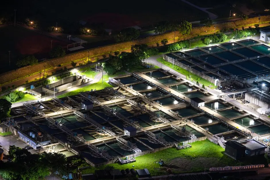
An MBBR is rarely the whole plant; it is almost always the middle of a train, and the wrong upstream or downstream unit will collapse its performance regardless of how well the carrier, fill, and HRT were specified. Upstream: coarse screening (≤6 mm) and grit removal protect carriers from ragging and abrasion; oil and grease must be removed by DAF before the MBBR or the biofilm fouls within weeks, which is why the DAF design parameters guide is a necessary companion to this one. Equalization is required for shock loads above 2× design OLR or where diurnal swings exceed 2× design flow; without it, the biofilm sloughs and effluent TSS spikes.
Downstream: the S5 Guheshwori study's 99.20% NH4-N and 96.84% COD figures are achievable on the MBBR alone, but sites targeting reuse, low total nitrogen, or strict TSS typically add a downstream MBR or cloth-media filter. Sludge handling is sized on the biofilm sloughing rate, not the influent TSS; the MBBR continuously sheds biomass, and the downstream solids train (lamella clarifier, plate-and-frame press) must be rated accordingly. For smaller industrial and commercial flows, a WSZ package plant with MBBR section consolidates screening, equalization, MBBR, and clarification in a buried skid. The waste activated sludge from the MBBR clarifier underflow is normally dewatered on a sludge dewatering press for MBBR waste activated sludge to 22–28% dry solids for off-site disposal.
Frequently Asked Questions
What fill fraction should I use for an industrial MBBR?
Industrial MBBRs typically run at 40–60% fill, with 67% as a practical upper limit above which fluidization degrades and carriers begin to bridge (Ødegaard, 2006, cited in S3). The S1 laundry study at 20% fill is useful as a baseline but is at the low end of the commercial range.
What dissolved oxygen setpoint protects nitrification in an MBBR?
Hold aerobic DO at 2–4 mg/L. Below 2 mg/L nitrification collapses, above 4 mg/L the blower is wasting power. Anoxic zones for denitrification should be held at <0.5 mg/L, as in the S2 leachate A2O-MBBR reactor. A properly sized MBBR is normally paired with a DAF oil and grease removal step upstream to keep the biofilm surface from fouling.
How do I size an MBBR reactor for combined BOD and nitrification?
Use the five-step method: required BOD removal (kg/d) ÷ OLR (g/m²·d) = biofilm area; biofilm area ÷ (carrier m²/m³ × fill fraction) = reactor volume; reactor volume ÷ flow = HRT. For a 500 m³/d, 800 mg/L BOD feed targeting 30 mg/L effluent, K3 carriers at 50% fill and 8 g BOD/m²·d gives ≈160 m³ of reactor at 7.7 h HRT, inside the A2O-MBBR band from S2. For strict ammonia or reuse targets, finish with an MBR polish downstream of the MBBR.