The Operator's Triage Card: Five Fault Signatures and Their Trigger Values
A multiple effect evaporator in 2026 should evaporate roughly 0.8n kg of water per kg of live steam — about 3.2 kg/kg on a 4-effect unit — yet installed systems consume 9.3 to 30.6 kJ/kg against a theoretical minimum of 3 to 7 kJ/kg (ScienceDirect 2025 review). Most of the gap is scaling, vacuum loss in the last effect, foaming carryover, tube leakage, and feed-flow imbalance. Diagnose by tracking per-effect ΔT against design, last-effect absolute pressure, and distillate conductivity; intervene when ΔT drifts more than 5 °C, vacuum rises above 20 kPa abs, or distillate conductivity climbs above 25 µS/cm.
Before opening a wrench, an operator needs a one-glance map. The five fault signatures below cover roughly 90% of MEE service calls (HydropureWater field data, 2026). Each signature is paired with the instrument to read first, the trigger value that converts a nuisance into an action item, and the section of this article where the full diagnostic ladder lives. Pin the table to the panel; the rest of the article is the reference behind it.
| Signature on the panel | Trigger value | Read first | Most likely cause | Go to |
|---|---|---|---|---|
| Per-effect ΔT falling from design | Drift > 5 °C = warning; > 8 °C = CIP trigger | Per-effect ΔT log vs. design ΔT | Scaling / fouling on tube walls | Scaling section |
| Last-effect absolute pressure rising | > 20 kPa abs on a 4–6 effect MEE | Last-effect pressure transmitter | Condenser, vacuum pump, or barometric leg | Vacuum section |
| Distillate conductivity climbing | > 25 µS/cm with stable ΔT | Distillate conductivity + TOC | Foaming / carryover at vapour head | Carryover section |
| Condensate conductivity step-change | 10× baseline within a single shift | Condensate conductivity probe | Tube leak (often last two effects) | Tube leak section |
| Inter-effect temperature profile inverted | Pressure cascade does not predict the ΔT pattern | Per-effect temperature + flow logs | Feed-flow / steam-distribution fault | Feed-flow section |
Fouling and Scaling: When the Heated Surface Stops Transferring Heat
Scaling and fouling account for the majority of unplanned downtime in industrial multiple effect evaporators (HydropureWater field data, 2026). The mechanism is straightforward: inverse-solubility salts — primarily CaSO₄, CaCO₃, and silica — precipitate on tube walls as water flashes off and concentrations climb, and organic foulants (polymerised antifoam residues, protein fragments, residual oils) layer on top of the mineral scale. A 0.5 mm CaSO₄ layer is enough to cut the overall heat transfer coefficient U by 30–50% and raise specific steam consumption proportionally.
Why forced-circulation MEE scales slower than falling-film tubes is captured by the Hugot correlation Uh,i = 0.007·Ti·(u/1.8)0.8 (per the MDPI 2020 paper on sugar-factory MEE, processes-08-00342): liquor velocity u enters to the 0.8 power, so doubling velocity in a forced circulation loop raises U by roughly 75% at the same saturation temperature. Falling-film tubes run at 1.5–2.0 m/s on the downflow film; once that film thins or patches, local U collapses. The diagnostic indicator is per-effect ΔT against design. Drift of more than 5 °C on any effect is a warning; drift above 8 °C triggers a scheduled CIP regardless of hours on the bundle.
Documented fix ladder, in escalation order: (1) review the anti-scalant program — dose, injection point, and compatibility with the brine chemistry; (2) run an on-line inhibited-acid wash for CaCO₃ if the metallurgy permits; (3) execute a scheduled CIP with rotation between alkaline detergent for organic fouling and inhibited acid (typically HCl with corrosion inhibitor or sulfamic acid) for mineral scale, with the chemistry matched to the deposit; (4) if U does not recover, pull the bundle for mechanical cleaning or replacement. Historical context: a 75 m³/day six-effect desalination plant ran in Egypt as early as 1912, and by the 1960s operators were already documenting that salt-deposit cleaning was the dominant cause of lost operating hours (ScienceDirect 2025). The technology is mature — the failure is operational, not design. Prevention in one line: hold ΔT within ±5 °C of design per effect and you will rarely see this section as an emergency.
Vacuum Loss in the Last Effect: The Easiest Fault to Diagnose and Most Often Mis-Attributed
Healthy last-effect absolute pressure for a 4–6 effect MEE is 8–15 kPa abs; rising above 20 kPa abs is the trigger to start the fix ladder. A 5 kPa loss raises the local boiling point by roughly 4 °C and inflates the boiling-point elevation penalty in the most concentrated effect, where the most viscous liquor sits. Capacity loss then propagates upstream because the last effect is the bottleneck of the train.
Three root causes account for roughly 90% of last-effect vacuum faults, ranked by frequency in the HydropureWater service database (2026): (1) condenser cooling-water fouling or flow loss, (2) vacuum pump seal water or steam supply, and (3) barometric leg seal loss or downstream drain restriction. They have different fixes, different crafts, and different response times — which is why mis-attribution wastes shifts.
The diagnostic step that separates them: with cooling-water flow and vacuum-pump steam supply held constant, observe last-effect pressure over 30 minutes. Fast drift (tens of minutes, pressure climbs in step changes) points to seal or leg; slow drift that tracks the cooling-water return temperature points to condenser fouling; stable but high pressure points to vacuum-pump capacity. Forward-feed MEE is more sensitive to vacuum loss because the warmest effect carries the thinnest liquor, and the train has no recovery margin — a backward-feed conversion partially absorbs vacuum loss by moving the most concentrated liquor to the warmest effect where viscosity is lowest. Reference the prevention matrix and the 2026 MEE retrofit and upgrade engineering guide before approving any vacuum-system rebuild, since the cheapest correction is often on the liquor side, not the vacuum side.
Foaming and Carryover: When the Distillate Tells You the Vapour Head Is Unstable
When distillate conductivity climbs above 25 µS/cm on a clean MEE with a stable ΔT profile, the cause is almost always mechanical or chemical at the vapour–liquid interface, not in the condenser. Surface-active organics — surfactants from textile scouring, antifoam residues from upstream reactors, protein fragments from pharma, residual FOG from food processing — stabilise bubbles that burst in the vapour head and entrain liquid droplets into the condenser. Rising distillate TOC confirms organic cause; visible haze in a grab sample confirms entrainment.
Four-step documented fix ladder: (1) defoamer selection — silicone-based for low-foam systems, fatty-alcohol (e.g. stearyl alcohol) for high-foam systems; (2) inspect and restore demister pads in the vapour head, since a plugged or dislodged pad is a common root cause and a free fix; (3) reduce vapour velocity in the entrainment separator below 1.5 m/s by trimming throughput or upgrading the separator; (4) pre-treat the feed to strip FOG and surfactants before evaporation — pairing the MEE with a DAF pre-treatment for industrial wastewater addresses the organic load at the front of the line and typically cuts carryover events by more than half. If carryover persists after all four, the underlying cause is feed chemistry, not equipment — redirect chemistry effort upstream rather than chasing the symptom at the condenser. For other membrane-style upstream systems that show similar conductivity-climb behaviour under load, the diagnostic pattern in the Forward Osmosis System Troubleshooting: 2026 Field Guide translates the same principles to flux-loss signatures.
Tube Leakage and Material Selection: The High-Consequence Fault That Material Upgrades Prevent
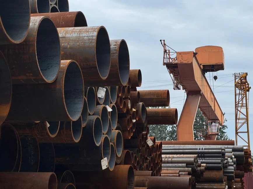
Tube leakage is rare but high-consequence. The signature is a sudden step-change in condensate conductivity — often 10× baseline within a single shift — or a rising liquor level in the downstream effect that does not match the feed rate. The root cause is almost always corrosion fatigue at the tube sheet, especially in the last two effects where chloride concentration routinely exceeds 10,000 mg/L on RO-reject and textile applications.
Response protocol: isolate the leaking effect, drain brine to holding, dump the downstream liquor to waste, replace or plug the leaking tube, restore after hydrotest at design pressure. Once brine is dumped, downstream solids handling typically runs through a plate and frame filter press for downstream solids handling to recover cake and clarify the centrate before it returns to the brine tank. The 2026 material-selection standard is to upgrade from 304SS to 2205 duplex or titanium in the last two effects whenever feed Cl⁻ exceeds 5,000 mg/L — this is now standard specification rather than an upgrade, particularly on pharmaceutical and high-salinity chemical brine. The CIP cost and lost production from a single tube-leak event typically justifies the material upgrade in one cycle, which is why the spec is moving upstream on the procurement side before the next bundle replacement. For plants with aerated upstream biology that can drive similar chloride-corrosion patterns on stainless surfaces, the Aeration Diffuser Fouling Troubleshooting: 2026 Field Guide documents the same alloy-vs-environment logic for aeration hardware.
Feed-Flow and Steam-Distribution Faults: When the Temperature Profile Inverts
When the inter-effect temperature profile does not match the pressure-cascade prediction — some effects running hot, others starved — the fault is feed-flow or steam distribution, not scaling. The distinguishing diagnostic: feed-flow faults produce a clean temperature inversion across the train with stable per-effect ΔT; scaling produces a localised ΔT collapse on one effect with a stable downstream profile. The two faults look similar on a poorly-instrumented panel and require opposite interventions — derime and clean for scaling, restore flow for feed faults — which is why the temperature-inversion pattern matters.
| Arrangement | Flow vs. steam | Best for | Weakness |
|---|---|---|---|
| Forward-feed | Co-current, natural flash | Non-scaling, low-viscosity feeds; no inter-effect pumps | Most sensitive to last-effect vacuum loss; warmest effect sees thinnest liquor |
| Backward-feed | Counter-current, requires inter-effect pumps | Viscous or scaling brines; highest log mean temperature difference for the same heating surface (per the MDPI 2020 paper, processes-08-00342) | Pump failure produces the temperature-inversion signature — fix the pump, not the heat balance |
| Cross-feed (parallel) | Feed split across effects | Batch operations with swinging concentration | Uncommon; higher piping complexity |
For 2026 retrofit on a forward-feed unit running a viscous or scaling brine, conversion to backward-feed by adding inter-effect pumps has a typical payback of 14–24 months on steam savings alone (HydropureWater field data, 2026). Pump failure on a backward-feed train produces the temperature-inversion signature from the triage card — fix the pump, not the heat balance, and the temperature profile recovers within one residence time.
Prevention Matrix and Retrofit Decision Framework
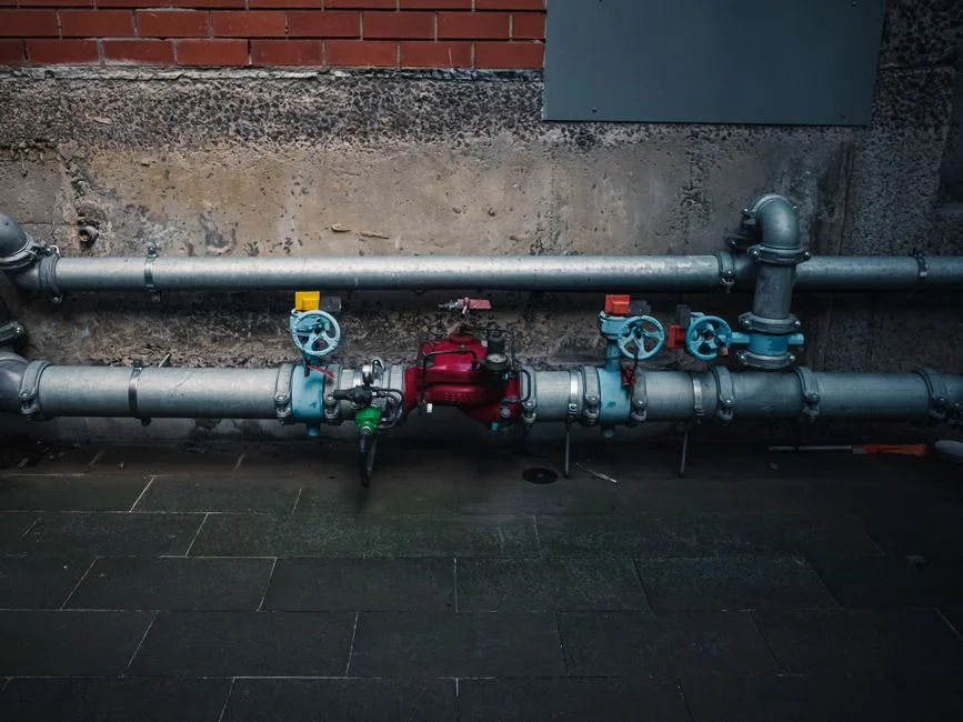
The cheapest MEE failure is the one that never happens. A 2026 prevention matrix for an industrial multiple effect evaporator on high-salinity wastewater has four levers: feed pre-treatment, anti-scalant program, scheduled CIP, and operating-window discipline — keep ΔT within ±5 °C of design per effect and you will rarely see a fault section of this article as an emergency. When the prevention matrix is no longer enough, three retrofit moves are technically and economically viable in 2026.
Ranked by payback band: (1) mechanical vapour recompression (MVR) — the largest single energy-savings move available, but it shifts cost from the steam header to the electrical bus, so the trade is right only when electricity is cheap and high-pressure steam is scarce; (2) thermal vapour recompression (TVC) — lower CAPEX, right for sites with surplus low-pressure steam that has no other use; (3) backward-feed conversion — smallest absolute steam savings but the shortest payback on the list (14–24 months on viscous or scaling brines, per HydropureWater field data, 2026). Tube-material upgrade is a fourth move, addressed in the leakage section above, not here. For full CAPEX ranges and the decision matrix behind these calls, the 2026 MEE retrofit and upgrade engineering guide is the reference document, and engineers ready to execute should pair it with the MEE installation and commissioning protocol so the new equipment is brought online against the same KPI dashboard used to diagnose the old one.
Frequently Asked Questions
What is the design steam economy of a multiple effect evaporator?
A multiple effect evaporator at design should evaporate roughly 0.8n kg of water per kg of live steam, where n is the number of effects. A clean 4-effect MEE sits at about 3.2 kg/kg; a 6-effect unit pushes close to 4.8 kg/kg. Steam economy below 2.0 kg/kg on a 4-effect unit is a fault condition requiring investigation; below 1.5 kg/kg is a shutdown trigger.
How do I know if my MEE is scaling versus foaming?
Scaling shows as falling ΔT across the affected effect at constant steam pressure, with steam economy dropping toward 0.5n or below. Foaming shows as rising distillate conductivity above 25 µS/cm and rising distillate TOC, with no change in ΔT profile. The two have opposite signatures on the same panel, which is why the triage card separates them into different readouts.
Can a forward-feed MEE be converted to backward-feed in 2026?
Yes. Conversion adds inter-effect pumps and re-pipes the liquor cross-overs, and is a 2026-standard retrofit. Typical payback is 14–24 months on steam savings alone for viscous or scaling brines (HydropureWater field data, 2026). The temperature-inversion signature is normal during commissioning and abnormal during operation; on a running backward-feed train, a temperature inversion is a pump problem, not a heat-balance problem.
How often should CIP be scheduled on a high-salinity MEE?
Every 200–400 operating hours for scaling feeds (RO reject, pharma brine, textile effluent), and 800+ hours for clean feeds. A ΔT drift greater than 8 °C from design value on any effect triggers CIP regardless of hours on the bundle, since the cost of a missed CIP is usually a tube-bundle replacement.
What vacuum should the last effect of a 4–6 effect MEE hold?
Healthy operating range is 8–15 kPa abs; rising above 20 kPa abs is the trigger to start the fix ladder. A 5 kPa loss raises local boiling point by roughly 4 °C and inflates the boiling-point elevation penalty in the most concentrated effect, propagating capacity loss upstream.