
Why Forward Osmosis Fails Differently Than Reverse Osmosis
Forward osmosis operates solely on the osmotic pressure differential between a concentrated draw solution and a lower-salinity feed, with no external hydraulic pressure applied across the membrane (per IntechOpen 2022; Membracon guide). The governing water flux equation is J_w = A(π_draw − π_feed − ΔP); because ΔP is effectively zero in FO, any decline in J_w directly reflects changes in π_draw (draw concentration drift), π_feed (fouling or scaling raising feed-side osmotic pressure), or A (membrane compaction or chemical damage) — not pump pressure as in RO. Solute flux follows J_s = B(ΔC) and produces reverse salt flux (RSF), an FO-specific failure indicator without an RO equivalent. This distinction alters the troubleshooting workflow: RO relies on pressure gauges, while FO depends on conductivities, flux, and osmotic pressure measurements. Hybrid FO-LPRO systems are established for polishing diluted seawater or brackish water at lower cost than standalone RO (per IntechOpen 2022), requiring FO troubleshooting to account for the coupled low-pressure RO stage downstream of the draw loop. The world's first commercial FO desalination plant at Al Najdah, Oman (per IntechOpen 2022) used a CA-FO membrane with a hypertonic glucose draw, and the same osmotic principles apply to every modern TFC FO element in 2026.
Symptom-to-Cause Matrix: What Your FO System Is Telling You
Use this matrix to diagnose issues: select the symptom from your shift log, perform the confirmation test, then proceed to the corrective action referenced. Diagnostic values align with the S4 lab protocol, where water permeability A (LMH/bar), salt permeability B (LMH), and salt rejection R are measured on a cross-flow RO rig at 0.28 bar applied pressure with 1.4 M NaCl feed. Repeat this test monthly to establish a membrane health baseline.
| Symptom | Probable Cause | Confirm With | First Action | Section Reference |
|---|---|---|---|---|
| Water flux decline 15-30% over 24-72 h | Concentration polarization, fouling, or scaling on feed side | Feed SDI, cross-flow velocity, osmotic pressure calculator output | Verify pretreatment, then run physical cleaning at doubled CFV | Diagnosing Flux Loss; CIP Recipes |
| Rising reverse salt flux (SRSF > 1 g/L) | Membrane damage, AL-FS orientation, or excessive draw concentration | Permeate conductivity, A/B test at 0.28 bar / 1.4 M NaCl | Recalibrate A and B; inspect for chemical damage | Controlling Reverse Salt Flux |
| Draw solution TDS drift ±10% setpoint | Draw recovery RO underperforming or RSF loading feed | Draw conductivity probe, RO concentrate flow | Isolate FO vs RO failure before adjusting either | Controlling Reverse Salt Flux |
| Feed-side pressure increase | Fouling layer resistance or support-layer clogging | Inlet vs outlet ΔP, feed SDI trend | Initiate CIP per foulant type | CIP Recipes |
| Permeate-side conductivity creep | Compromised membrane integrity, seal failure | Permeate conductivity probe, integrity test | Pressure decay or marker dye test; plan replacement | Diagnosing Flux Loss; Preventive Maintenance |
| Membrane element discoloration | Oil wetting, biofouling, or chemical attack | Visual inspection on shutdown, foulant analysis | Match CIP chemistry to foulant; replace if oil-wet | Stream-Specific Watch-Outs; CIP Recipes |
Diagnosing Flux Loss: Pretreatment, Concentration Polarization, and Membrane Health
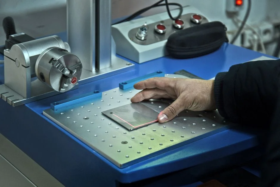
Address flux loss by following a cost-effective diagnostic sequence. First, verify feed pretreatment: SDI should remain below 3 for FO operation; spikes above 5 correlate with accelerated fouling in field data and require immediate DAF or media filter backwash. Next, check feed temperature and concentration: π_feed increases with both TDS and temperature, reducing the driving force (π_draw − π_feed) and lowering flux by roughly 2% per °C. Then, measure concentration polarization: internal CP within the porous support layer is the primary FO-specific flux limiter, most severe in AL-FS orientation where the support faces the feed. Switching to AL-DS orientation or increasing cross-flow velocity mitigates CP — the S4 protocol reversed fouling on their FO test rig by doubling CFV for 30 minutes during physical cleaning. Finally, assess membrane health: measure A, B, and R on a cross-flow RO rig at 0.28 bar with 1.4 M NaCl feed (per S4). If A has dropped more than 25% from the commissioned baseline, schedule membrane replacement instead of another CIP. Conduct this A/B/R characterization monthly; the cost of one lab test is negligible compared to an unplanned membrane changeout on a 70,000 ppm draw loop.
Controlling Reverse Salt Flux and Draw Solution Imbalance
Specific reverse salt flux (SRSF = J_s / J_w, in g/L) serves as the most diagnostic metric unique to FO. Industrial FO systems typically maintain SRSF below 0.5-1.0 g/L; values exceeding 2 g/L indicate uneconomic draw top-up costs and feed contamination. SRSF increases with higher draw concentration, fouled or chemically damaged membranes, AL-FS orientation, and elevated feed temperature, often signaling upstream changes before flux loss becomes apparent. The draw recovery unit stabilizes the loop: most commercial plants use an RO tuned to 70,000 ppm TDS, while advanced systems handle up to 250,000 ppm (per Membracon guide). Operating outside this range destabilizes the draw loop. If draw TDS drifts, isolate the failure before making adjustments: high permeate conductivity with drifting draw suggests a compromised FO membrane, while stable permeate with drifting draw points to the recovery RO. For details on the coupled RO stage, see the RO membrane system working principle guide, as the same flux-vs-pressure principles apply beyond the FO membrane.
CIP Recipes and Cleaning Frequency for FO Membranes
Select cleaning chemistry based on the foulant and confirm effectiveness with flux recovery exceeding 95% before returning the element to service. The S4 protocol demonstrated that physical cleaning at doubled cross-flow velocity for 30 minutes successfully reversed fouling on their graphene-quantum-dot TFC FO membrane without chemicals — attempt this first before chemical CIP.
| Foulant Type | Detergent / Chelant | Typical Concentration | pH Window | Contact Time | Temperature |
|---|---|---|---|---|---|
| Organic / biofouling | Alkaline detergent + non-ionic surfactant | 0.5-1.0 wt% | 10-12 | 60-90 min soak | 30-35 °C |
| Scaling (Ca, Mg, silica) | Citric acid or EDTA-based chelant | 1-2 wt% citric, 0.5-1.0 wt% EDTA | 2-4 | 60 min circulation | 30-45 °C |
| Oil / grease | Anionic surfactant + alkaline builder | 0.5-1.0 wt% | 10-11 | 60 min | 35-40 °C |
| Sulfide / heavy metal | Oxidant (H₂O₂) + chelant | 0.1-0.3 wt% H₂O₂ | 6-8 | 45 min | 25-30 °C |
Flush thoroughly with permeate after any acid or surfactant CIP before repressurizing the draw loop. A reverse salt flux spike immediately after cleaning usually indicates membrane chemical damage — recalibrate A and B values before trusting the recovered flux. If recovery remains below 90%, replace the membrane rather than using more aggressive chemistry.
Stream-Specific Watch-Outs: Oily, Dairy, Produced Water, and Tannery Effluents
FO has been tested on municipal sewage, oily wastewater, dairy streams, produced water, tannery effluent, and automobile effluents (per IntechOpen 2022), but each stream presents unique failure modes. Oily wastewater requires DAF pretreatment to reduce oil-in-water below 10 mg/L; once a membrane becomes oil-wet, it is generally unrecoverable. Dairy streams combine high organic load with calcium phosphate scaling, necessitating biological COD reduction and scheduled acid CIP every 5-7 days instead of waiting for flux alarms. Produced water is dominated by silica and barium sulfate scaling — blend with a low-silica stream, dose antiscalant, and expect more frequent CIP than in municipal applications. Tannery effluent combines high salinity with chrome, requiring verification of membrane chemical compatibility before selecting any CIP recipe, as chrome can cross-link with organics and permanently blind the support layer. These high-fouling streams justify PLC-controlled chemical dosing instead of manual top-ups.
Preventive Maintenance Cadence and When to Escalate
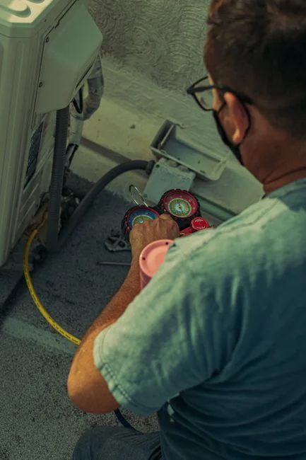
Implement a scheduled maintenance program to detect issues before flux drops below 70% of the commissioned baseline. Daily: log draw TDS, feed conductivity, water flux, and reverse salt flux; trend these values weekly against the baseline. Weekly: verify pretreatment performance — SDI, DAF skimmer operation, and chemical dosing rates — and correct any drift. Monthly: conduct a full A/B/R membrane characterization on a cross-flow RO rig at 0.28 bar with 1.4 M NaCl feed, comparing results to commissioned values. Quarterly: perform a CIP regardless of symptoms on high-fouling streams (oily, dairy, produced water) to stay ahead of fouling. Escalation triggers include flux below 70% of baseline after a confirmed CIP, SRSF above 2 g/L, or draw TDS drift exceeding 10% from setpoint. Each of these signals may involve the draw recovery RO skid, which should be checked in parallel. For a related membrane process guide, see the ultrafiltration system troubleshooting playbook.
Frequently Asked Questions
What is the most common cause of flux loss in an FO system?
Concentration polarization inside the support layer, worsened by feed-side fouling. Operate in AL-DS orientation and perform physical cleaning at doubled cross-flow velocity for 30 minutes before considering chemical CIP — S4 field data showed fouling reversal without chemicals under this protocol.
How is reverse salt flux measured and what is acceptable?
SRSF is calculated as J_s divided by J_w in g/L, with 0.5-1.0 g/L typical for well-managed industrial FO systems. Treat values above 2 g/L as an escalation trigger, and pair the SRSF trend with a monthly A/B test at 0.28 bar with 1.4 M NaCl feed to confirm membrane integrity.
Can FO treat oily or dairy wastewater directly?
No. Oily streams require DAF pretreatment to reduce oil-in-water below 10 mg/L, and dairy streams need biological COD reduction plus scheduled acid CIP. Both are included in the commercial FO wastewater portfolio (per IntechOpen 2022) but only with proper upstream conditioning.
When should I clean my FO membrane vs replace it?
Clean when flux