What You Are Actually Maintaining in an MBBR
An MBBR maintenance guide in 2026 is a tiered schedule of daily, weekly, monthly, and annual tasks covering dissolved-oxygen control (2–4 mg/L for BOD removal, 4–6 mg/L for nitrification), carrier fill-fraction checks (typically 30–70% of empty reactor volume), sieve inspection, biofilm thickness management, and aeration grid cleaning. Following the schedule keeps COD removal above 90% and prevents the three most common failures — carrier washout, biofilm sloughing, and aeration dead zones.
An MBBR is a hybrid of activated sludge and fixed-film biology: buoyant HDPE carriers, typically 10–25 mm with a minimum specific surface area of 200–250 m²/m³, are held in suspension by aeration rather than packed into a fixed bed (S3, S5). The mixed liquor suspended solids sit at roughly 3–4 kg SS/m³, comparable to a conventional activated-sludge tank, but the fixed biomass on carriers can reach 10,000–12,000 mg/L — that attached fraction is the asset you are protecting (S5).
You are maintaining four subsystems. First, the carriers themselves: their physical inventory, geometry, and buoyancy. Second, the biofilm on those carriers, which follows a four-stage life cycle of initial adhesion (reversible, driven by van der Waals and electrostatic forces), irreversible EPS bonding, maturation into a three-dimensional stratified layer, and finally sloughing — the natural reset that keeps the film diffusion-limited and active (S3). Third, the aeration grid that keeps the carriers fluidized and supplies oxygen. Fourth, the outlet sieves whose mesh must be smaller than the smallest carrier dimension to retain the media in the basin (S3). For broader context on how an MBBR fits into a packaged plant, see the WSZ underground integrated sewage treatment unit and the MBR integrated wastewater treatment equipment pages.
Daily and Weekly Maintenance Tasks
Daily maintenance prevents Friday-afternoon DO alarms through two log entries and a 5-minute walk-around.
Daily tasks run at the same time as your morning rounds. Log influent flow, pH, temperature, dissolved oxygen in each reactor zone, and effluent TSS; flag any DO reading outside 2–6 mg/L immediately because the biofilm below 2 mg/L begins to lose nitrification capacity (S5). Then walk the length of the reactor and look for three things: carrier buildup against tank walls, foaming at the surface, and any oil or chemical sheen. Each of those visual cues points to a different failure mode — wall buildup means mixing has stalled, foaming means the F/M ratio is wrong or surfactants are arriving in the influent, and a sheen is the earliest signal of a toxic slug that will detach biofilm within hours (S3).
Weekly tasks close the loop on the daily readings. Verify carrier fill fraction by counting visible carriers in a 1 m² grid marked on the tank surface — the design target is 30–70% of the empty reactor volume depending on whether the zone is configured for carbon removal (50–60%) or nutrient removal (30–40%) (S5). Clean the DO probe with the manufacturer's solution and verify blower output pressure against the commissioning baseline; a 10% drop typically means a diffuser is partially plugged. Skim any floating scum off the carrier layer so anaerobic pockets cannot form underneath it (S3). Finally, pull an effluent sample for a 30-minute settled-sludge volume test — a sudden rise usually means biomass is washing out rather than staying attached.
Monthly and Annual Maintenance Tasks

Monthly work targets components that fail slowly enough to be invisible on a daily log.
Inspect every outlet sieve: look for fouling, biofilm bridging, or mechanical damage, then clean with a soft brush and low-pressure rinse — never a high-pressure jet, which strips the protective biofilm layer off the sieve itself and can crack welds (S3). Walk the aeration grid with the blower locked out and check each diffuser for plugging or an uneven bubble pattern; replace individual diffusers rather than the whole grid whenever the frame is still serviceable.
Take a representative carrier sample, weigh it wet, dry it to constant weight, and reweigh to back-calculate biofilm thickness. Films below about 50 µm mean the reactor is under-loaded; films above 300 µm mean excess biomass and rising sludge loss to the effluent (S3). Quarterly, verify the carrier count against the design inventory and top up to the design fill — industry practice assumes 1–5% annual loss to washout and attrition, so a small working stock of spare K1 or K5 carriers is cheap insurance (S5). For downstream solids handling, a plate-frame filter press is the usual companion to an MBBR.
Annual tasks should be scheduled into a planned outage. Drain one reactor zone if the hydraulic profile allows it, then inspect the carriers for wear, cracking, or biofilm calcification, and photograph the aeration piping for comparison against the commissioning baseline; corrosion here is the leading predictor of a mid-cycle failure (S3). Recalibrate every online probe — DO, pH, and conductivity — against a lab DO meter (Winkler or luminescent) and a portable pH/conductivity unit. The calibration log is also the document an auditor will ask for first.
Operating Setpoints You Should Know by Heart
The table below consolidates the setpoints an operator should be able to recite without flipping through a manual. Values are drawn from S5 (hybrid MBBR review) and S3 (process description), with cold-weather behaviour from the Andreottola et al. 2000b cold-region MBBR study cited in S2.
| Parameter | Typical Range | Operator Note |
|---|---|---|
| HRT — BOD removal | 4–8 h | Shorter end for high-rate carbon removal |
| HRT — nitrification | 6–12 h | Extend to 12+ h below 12 °C |
| Dissolved oxygen — BOD zone | 2–4 mg/L | Below 2 mg/L heterotrophs lose capacity |
| Dissolved oxygen — nitrification zone | 4–6 mg/L | Nitrification collapses below 2 mg/L |
| Carrier fill — carbon removal | 50–60% | K1 media ~500 m²/m³, K5 ~800 m²/m³, Mutag BioChip ~1200 m²/m³ (S5) |
| Carrier fill — nutrient removal | 30–40% | Up to 70% max; minimum 200–250 m²/m³ specific surface area (S5) |
| pH | 6.5–8.5 | Nitrification slows sharply below 7.0 (S3) |
| Temperature | 10–35 °C | Expect 30–50% rate reduction below 10 °C (Andreottola 2000b) |
| MLSS in reactor | 3,000–5,000 mg/L | Most active biomass is fixed, not suspended (S5) |
| Target COD removal | ≥90% | Benchmarks: 91% BOD / 93.81% COD at day 10 in S1 (K1, 20% fill) |
When a value drifts outside these ranges, the biofilm responds within hours. The setpoints are not independent: dropping DO to save blower power will also drop nitrification, and raising fill fraction above 60% without raising airflow just creates dead zones.
Troubleshooting the Five Most Common MBBR Problems
Use the matrix below when an alarm fires to identify the root cause and the first check to run on shift.
| Symptom | Likely Cause | First Check on Shift |
|---|---|---|
| Effluent COD or NH3-N rising | DO too low; biofilm over-thick and sloughing; toxic influent shock (S3) | Recalibrate DO probe; check blower output pressure; review influent pH and temperature trend |
| Carrier washout at the outlet | Sieve mesh hole; sieve lifted off seat; hydraulic surge (S3) | Lower reactor water level to design; inspect each sieve for damage — mesh must be smaller than the smallest carrier dimension |
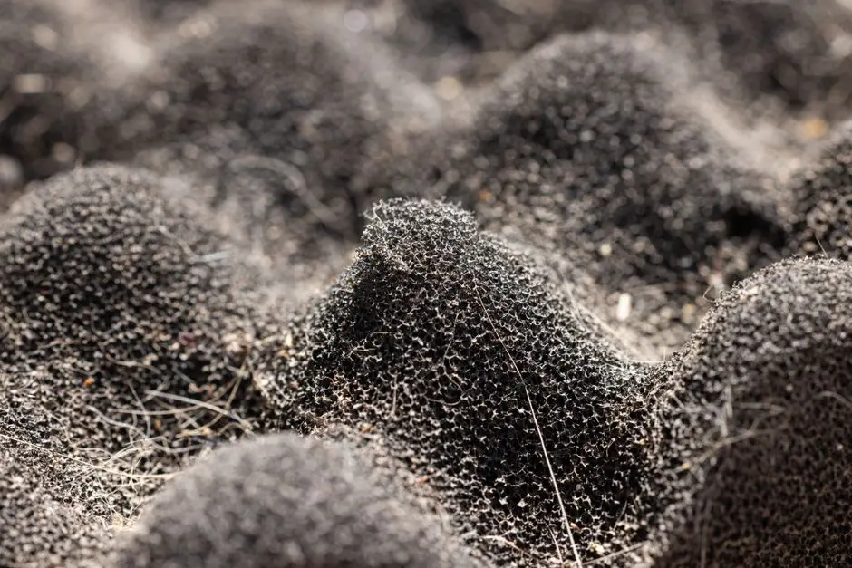
| White or grey biofilm instead of brown | Young biofilm; sulfur-oxidizing bacteria; toxic kill (S3) | Reseed with healthy activated sludge; sample influent for H2S or chlorinated solvents |
| Carriers clumping and sinking | Biofilm overgrowth; fouling; scale buildup (S3) | Increase air supply to raise shear; pull and weigh a carrier; consider low-dose chlorine cleaning (≤5 mg/L) |
| Foaming on reactor surface | High F/M; surfactant-rich influent; young biofilm | Reduce organic loading; verify antifoam compatibility with downstream DAF pre-treatment ahead of the MBBR; check Wasting rate |
Two of those symptoms — rising COD and clumping carriers — share a root cause: biofilm overgrowth. The fix requires more shear, more DO, and less feed, but the first-check column identifies the specific immediate action needed.
Start-Up and Re-Start After Shutdown
Bringing an MBBR back online requires a specific seeding window to ensure success.
Seed the reactor with healthy activated sludge at 2,000–3,000 mg/L MLSS, then run at low organic loading for 15 days to let the biofilm establish — the S1 laundry wastewater study used exactly that 15-day seeding window with 20% K1 fill (S1). Hold DO at the upper end of the setpoint, 5–6 mg/L, during seeding so heterotrophs colonize the carriers before nitrifiers have to compete for surface area (S3).
After seeding, ramp the feed gradually to design loading and expect 7–10 days to reach nameplate removal — the same S1 study hit 91% BOD and 93.81% COD by day 10 of processing (S1). Treat any shutdown longer than 48 hours as a mini-commissioning: re-check carrier fill, walk the sieves, and recalibrate the DO probe before resuming feed. A pH/alkalinity trim during the first 72 hours of restart, dosed through an automatic chemical dosing system, prevents the nitrification-driven pH dip that otherwise stalls a fresh biofilm.
Frequently Asked Questions
How often do I need to top up MBBR carrier media?
Plan on 1–5% top-up per year to replace carriers lost to washout and attrition (S5). Verify by counting carriers in a 1 m² grid on the tank surface each quarter and comparing to the design fill fraction of 30–70%.
What dissolved oxygen setpoint should I run for nitrification?
Hold 4–6 mg/L in the nitrification zone and 2–4 mg/L in the BOD zone. Nitrification collapses below 2 mg/L, so if you can only run one DO reading across the train, target 4 mg/L minimum (S5).
What does a healthy MBBR biofilm look like?
A mature, healthy biofilm is golden-brown and slimy to the touch. White or grey film usually means a young or stressed biofilm, often from toxic influent or sulfur-oxidizing bacteria (S3).
How do I clean an MBBR outlet sieve without killing the biofilm?
Use a soft brush and low-pressure rinse only. High-pressure jets strip the protective biofilm off the sieve surface and can crack welds, accelerating future fouling (S3).
What is the fastest safe way to re-start an MBBR after a toxic shock?
Stop the feed, raise DO to 5–6 mg/L, and reseed with 2,000–3,000 mg/L MLSS of healthy activated sludge. Expect 7–10 days to recover 90%+ COD removal once the biofilm re-establishes (S1).
Related Equipment
- automatic chemical dosing system — specifications, capacity range, and technical data
- DAF pre-treatment ahead of the MBBR — specifications, capacity range, and technical data